Mitsubishi Eclipse / Eclipse Spyder (2000-2002). Service and repair manual - part 454


  Index      Mitsubishi     Mitsubishi Eclipse / Eclipse Spyder (2000-2002). Service and repair manual


Search            


Content   ..  452  453  454  455   ..


Mitsubishi Eclipse / Eclipse Spyder (2000-2002). Service and repair manual - part 454


AUTOMATIC TRANSAXLE DIAGNOSIS

TSB Revision

AUTOMATIC TRANSAXLE

23A-107

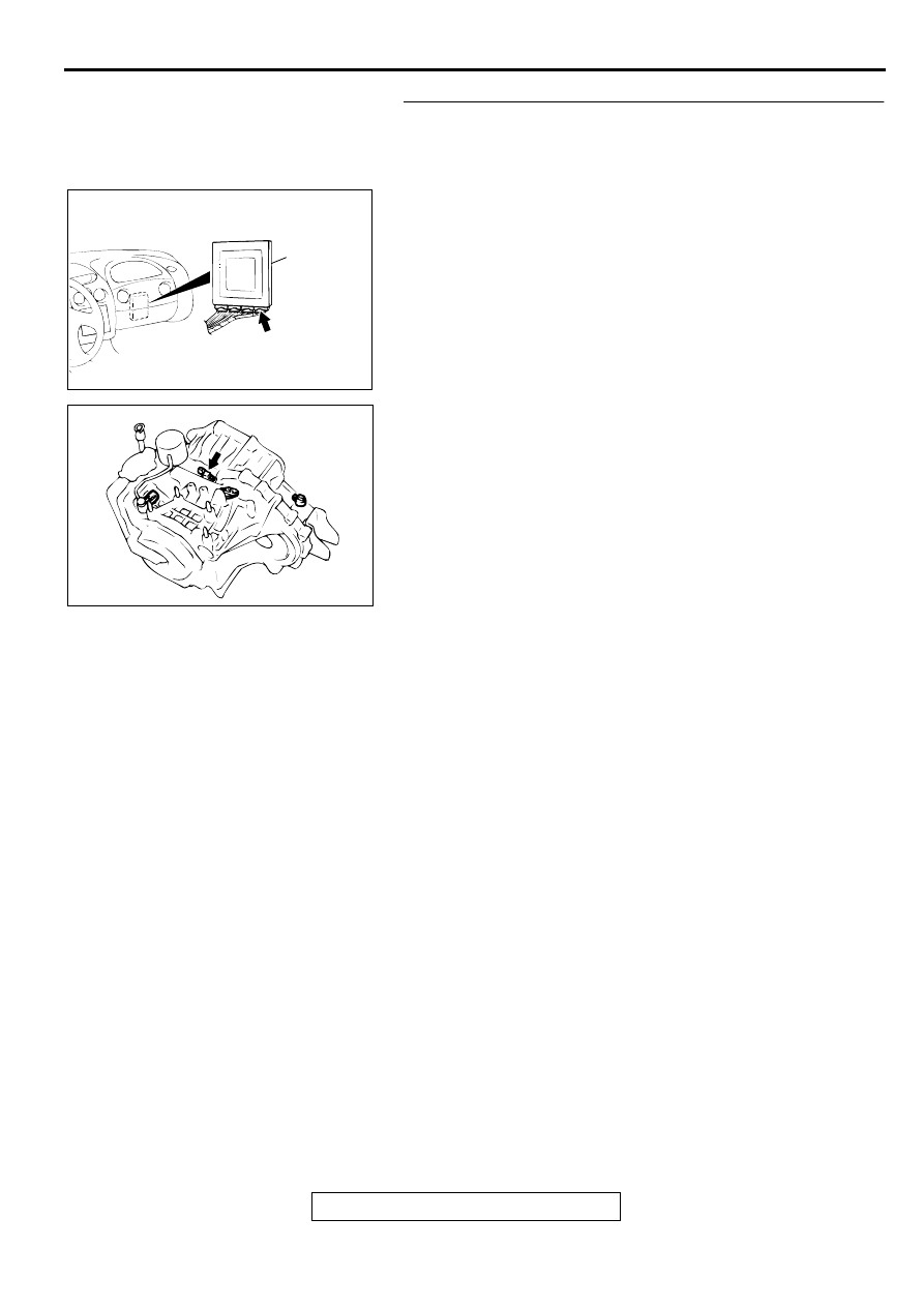
STEP 7. Check harness for short circuit to ground between 
PCM connector C-61 <2.4L Engine> or C-63 <3.0L Engine> 
terminal 103 and input shaft speed sensor connector B-42 
terminal 2.
Q: Is the harness wire in good condition?

YES : Go to Step 4.
NO :  Repair it.

AC001657

CONNECTOR: C-61 <2.4L ENGINE> OR
C-63 <3.0L ENGINE>

PCM

AN

AC001835

CONNECTOR: B-42

AD

AUTOMATIC TRANSAXLE DIAGNOSIS

TSB Revision

AUTOMATIC TRANSAXLE

23A-108

STEP 8. Using the oscilloscope, check the waveform at 
PCM connectors C-54 <2.4L Engine> or C-55 <3.0L 
Engine> and C-61 <2.4L Engine> or C-63 <3.0L Engine> by 
backprobing.
(1) Do not disconnect connectors C-54 <2.4L Engine> or C-55 

<3.0L Engine> and C-61 <2.4L Engine> or C-63 <3.0L 
Engine>.

(2) Connect an oscilloscope probe to PCM connector C-54 

<2.4L Engine> or C-55 <3.0L Engine> terminal 57 and to 
PCM connector C-61 <2.4L Engine> or C-63 <3.0L Engine> 
terminal 103 by backprobing.

(3) Start the engine and run at constant speed of 50km/h 

(31mph). (Gear range: 3rd gear)

(4) Check the waveform.

The waveform should show a pattern similar to the 
illustration. The maximum value should be 4.8 volts and 
more and the minimum value 0.8 volts and less. The 
output waveform should not contain the noise.

(5) Turn the ignition switch to "LOCK" (OFF) position.

Q: Is the waveform normal?

YES : Go to Step 9.
NO :  Go to Step 10.

STEP 9. Check connectors C-54 <2.4L Engine> or C-55 
<3.0L Engine> and C-61 <2.4L Engine> or C-63 <3.0L 
Engine> at PCM for damage.
Q: Are the connectors in good condition?

YES : Go to Step 4.
NO :  Repair or replace it. Refer to GROUP 00E, Harness 

Connector Inspection 

P.00E-2

.

AC001657

CONNECTORS: C-54 <2.4L ENGINE> OR
C-55 <3.0L ENGINE>, C-61 <2.4L ENGINE>
OR C-63 <3.0L ENGINE>

PCM

AM

C-54 <2.4L ENGINE> 
OR
C-55 <3.0L ENGINE>

C-61 <2.4L ENGINE>
OR 
C-63 <3.0L ENGINE>

AC001899

C-61 <2.4L ENGINE> OR C-63 <3.0L ENGINE>
CONNECTOR HARNESS  SIDE VIEW

C-54 <2.4L ENGINE> OR C-55 <3.0L ENGINE>
CONNECTOR HARNESS SIDE VIEW

AD

OSCILLO-
SCOPE

PROBE

ACX02131

NORMAL WAVEFORM

AB

(V)

5

0

AC001657

CONNECTORS: C-54 <2.4L ENGINE> OR
C-55 <3.0L ENGINE>, C-61 <2.4L ENGINE>
OR C-63 <3.0L ENGINE>

PCM

AM

C-54 <2.4L ENGINE> 
OR
C-55 <3.0L ENGINE>

C-61 <2.4L ENGINE>
OR 
C-63 <3.0L ENGINE>

AUTOMATIC TRANSAXLE DIAGNOSIS

TSB Revision

AUTOMATIC TRANSAXLE

23A-109

STEP 10. Check connectors C-54 <2.4L Engine> or C-55 
<3.0L Engine> and C-61 <2.4L Engine> or C-63 <3.0L 
Engine> at PCM and B-42 at input shaft speed sensor for 
damage.
Q: Are the connectors in good condition?

YES : Go to Step 11.
NO :  Repair or replace it. Refer to GROUP 00E, Harness 

Connector Inspection 

P.00E-2

.

STEP 11. Check the continuity at input shaft speed sensor 
connector B-42.
(1) Disconnect connector B-42 and measure at the harness 

side.

(2) Check for the continuity between terminal 1 and ground.

Should be less than 2 ohm.

Q: Is the continuity normal?

YES : Go to Step 12.
NO :  Repair it because of harness open circuit or damage 

between input shaft speed sensor connector B-42 
terminal 1 and PCM connector C-54 <2.4L Engine> or 
C-55 <3.0L Engine> terminal 57.

AC001657

CONNECTORS: C-54 <2.4L ENGINE> OR
C-55 <3.0L ENGINE>, C-61 <2.4L ENGINE>
OR C-63 <3.0L ENGINE>

PCM

AM

C-54 <2.4L ENGINE> 
OR
C-55 <3.0L ENGINE>

C-61 <2.4L ENGINE>
OR 
C-63 <3.0L ENGINE>

AC001835

CONNECTOR: B-42

AD

AC001835

CONNECTOR: B-42

AD

ACX02128

HARNESS
CONNECTOR: B-42

AE

AUTOMATIC TRANSAXLE DIAGNOSIS

TSB Revision

AUTOMATIC TRANSAXLE

23A-110

STEP 12. Check the sensor output voltage at input shaft 
speed sensor connector B-42.
(1) Disconnect connector B-42 and measure at the harness 

side.

(2) Turn the ignition switch to "ON" position.

(3) Measure the voltage between terminal 2 and ground.

Voltage should be between 4.8 and 5.2 volts.

(4) Turn the ignition switch to "LOCK" (OFF) position.

Q: Is the voltage normal?

YES : Go to Step 13.
NO :  Repair it because of harness open circuit or damage 

between input shaft speed sensor connector B-42 
terminal 2 and PCM connector C-61 <2.4L Engine> or 
C-63 <3.0L Engine> terminal 103.

STEP 13. Check the power supply voltage at input shaft 
speed sensor connector B-42.
(1) Disconnect connector B-42 and measure at the harness 

side.

(2) Turn the ignition switch to "ON" position.

(3) Measure the voltage between terminal 3 and ground.

Voltage should be battery positive voltage.

(4) Turn the ignition switch to "LOCK" (OFF) position.

Q: Is the voltage normal?

YES : Go to Step 15.
NO :  Go to Step 14.

AC001835

CONNECTOR: B-42

AD

ACX02127

HARNESS
CONNECTOR: B-42

AE

AC001835

CONNECTOR: B-42

AD

ACX02126

HARNESS
CONNECTOR: B-42

AE


Content   ..  452  453  454  455   ..