Mitsubishi Eclipse / Eclipse Spyder (2000-2002). Service and repair manual - part 195


  Index      Mitsubishi     Mitsubishi Eclipse / Eclipse Spyder (2000-2002). Service and repair manual


Search            


Content   ..  193  194  195  196   ..


Mitsubishi Eclipse / Eclipse Spyder (2000-2002). Service and repair manual - part 195


ON-VEHICLE SERVICE

TSB Revision

MULTIPORT FUEL INJECTION (MFI) <2.4L ENGINE>

13A-479

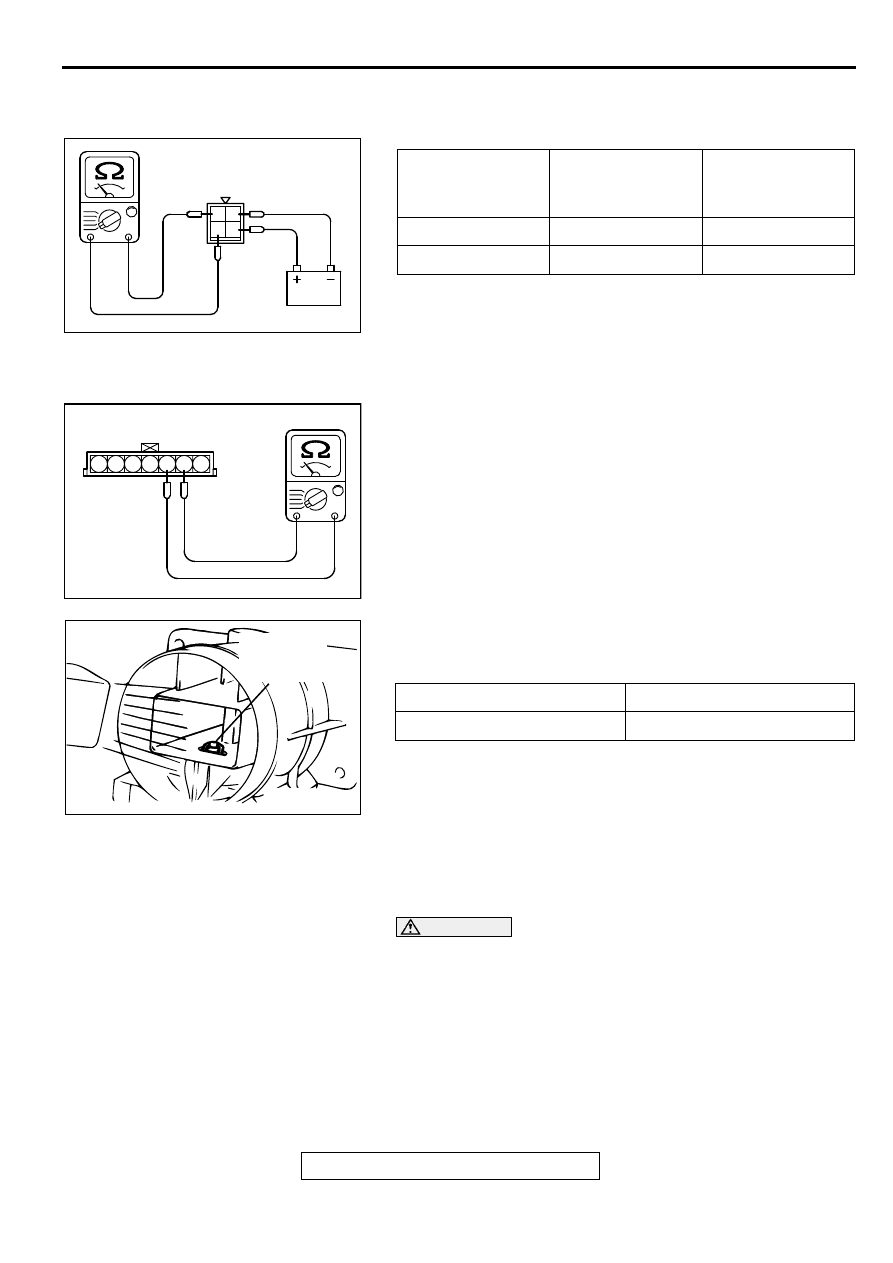
MULTIPORT FUEL INJECTION (MFI) RELAY AND 
FUEL PUMP RELAY CONTINUITY CHECK

M1131009900061

INTAKE AIR TEMPERATURE SENSOR CHECK

M1131002800052

1. Disconnect the volume air flow sensor connectors.

2. Measure resistance between terminals 5 and 6.

Standard value:

5.3 

 6.7 k

 [at 0

°

C (32

°

F)]

2.3 

 3.0 k

 [at 20

°

C (68

°

F)]

1.0 

 1.5 k

 [at 40

°

C (104

°

F)]

0.30 

 0.42 k

 [at 80

°

C (176

°

F)]

3. If not within specifications, replace the volume air flow 

sensor.

4. Measure resistance while heating the sensor using a hair 

dryer.

Normal condition:

5. If resistance does not decrease as heat increases, replace 

the volume air flow sensor assembly.

ENGINE COOLANT TEMPERATURE SENSOR 
CHECK

M1131003100056

CAUTION

Be careful not to touch the connector (resin section) with 
the tool when removing and installing.
1. Drain engine coolant, then remove the engine coolant 

temperature sensor.

BATTERY 
VOLTAGE

BATTERY POWER 
SUPPLY 
TERMINAL

SPECIFIED 
CONDITION

Not supplied

-

2-4

Supplied

2-41-3

AKX01433

MFI RELAY SIDE
CONNECTOR

1 2

4

3

AB

AKX01407AB

INTAKE AIR TEMPERATURE
SENSOR SIDE CONNECTOR

1 2 3 4 5 6 7

TEMPERATURE

RESISTANCE (k

)

Higher

Smaller

AKX01621 AB

INTAKE AIR
TEMPERATURE
SENSOR

ON-VEHICLE SERVICE

TSB Revision

MULTIPORT FUEL INJECTION (MFI) <2.4L ENGINE>

13A-480

2. With the temperature sensing portion of engine coolant 

temperature sensor immersed in hot water, check the 
resistance.

Standard value:

5.1 

 6.5 k

 [at 0

°

C (32

°

F)]

2.1 

 2.7 k

 [at 20

°

C (68

°

F)]

0.9 

 1.3 k

 [at 40

°

C (104

°

F)]

0.26 

 0.36 k

 [at 80

°

C (176

°

F)]

3. If resistance deviates from the standard value greatly, 

replace the sensor.

4 . Apply 3M

 AAD part number 8731 or equivalent to threaded 

portion.

5. Install the engine coolant temperature sensor and tighten it 

to the specified torque.

Tightening torque: 29 

±

 10 N

m (22 

±

 7 ft-lb)

THROTTLE POSITION SENSOR CHECK

M1131003200105

Required Special Tool:
MB991348: Test Harness Set
Checking the Terminal Resistance
1. Disconnect the throttle position sensor connector.

2. Measure resistance between the throttle position sensor 

side connector terminal 1 and terminal 4.

Standard value: 3.5 

 6.5 k

3. Measure resistance between the throttle position sensor 

side connector terminal 1 and terminal 3.

Normal condition:

4. If resistance is outside the standard value, or if it doesn't 

change smoothly, replace the throttle position sensor.

NOTE: After replacement, the throttle position sensor should 
be adjusted. (Refer to 

P.13A-473

.)

AKX01622

AKX01623 AB

Throttle valve slowly open 
until fully open from the idle 
position

Changes smoothly in 
proportion to the opening 
angle of the throttle valve

AKX01413

THROTTLE POSITION
SENSOR CONNECTOR

1 2 3 4

AB

ON-VEHICLE SERVICE

TSB Revision

MULTIPORT FUEL INJECTION (MFI) <2.4L ENGINE>

13A-481

Check using oscilloscope
1. Disconnect the throttle position sensor connector and 

connect the test harness special tool (MB991348) in 
between.(All terminals should be connected.)

2. Connect the oscilloscope probe to the throttle position 

sensor side connector terminal 3.

3. Turn the ignition switch "ON" position.

4. Slowly move the throttle lever from the idle position to the 

full-throttle position and check then if the waveform is free 
from any noise.

5. If any noise is recognized, replace the throttle position 

sensor.

NOTE: After replacement, the throttle position sensor should 
be adjusted. (Refer to 

P.13A-473

.)

HEATED OXYGEN SENSOR CHECK

M1131005000129

Required Special Tools:
MB991658: Test Harness Set
MD998464: Test Harness
<Heated oxygen sensor (rear)>
1. Using scan tool MB991502, observe HO

2

S reading. If 

values are unsatisfactory, or if Scan tool is not available, use 
the following procedure:

(1) Disconnect the heated oxygen sensor connector and 

connect special tool MB991658 to the connector on the 
heated oxygen sensor side.

(2) Make sure that there is continuity [11-18 

 at 20

°

C

 (68°


F)] between terminal 3 and terminal 4 on the heated 
oxygen sensor connector

(3) If there is no continuity, replace the heated oxygen 

sensor.

(4) Warm up the engine until engine coolant is 80

°

 C (176

°

F

or higher.

CAUTION

Be very careful when connecting the jumper wires; 
incorrect connection can damage the heated oxygen 
sensor.

(5) Use the jumper wires to connect terminal 3 of the heated 

oxygen sensor connector to the positive battery terminal 
and terminal 4 to the negative battery terminal.

(6) Connect a digital voltage meter between terminal 1 and 

terminal 2.

2. While repeatedly revving the engine, measure the heated 

oxygen sensor output voltage.

AKX01461AB

THROTTLE POSITION
SENSOR CONNECTOR

OSCILLOSCOPE

1 2 3 4

AKX01462AB

NORMAL WAVEFORM

THROTTLE LEVER
FULL-THROTTLE
POSITION

THROTTLE
LEVER
IDLE
POSITION

AK000121AB

HEATED OXYGEN SENSOR
EQUIPMENT SIDE CONNECTOR

MB991658

AK000122

JUMPER
WIRES

MB991658

AB

ON-VEHICLE SERVICE

TSB Revision

MULTIPORT FUEL INJECTION (MFI) <2.4L ENGINE>

13A-482

Standard value:

3. If the sensor is defective, replace the heated oxygen sensor.

NOTE: For removal and installation of the heated oxygen 
sensor, refer to GROUP 15, Exhaust Pipe and Main Muffler 

P.15-19

.

<Heated oxygen sensor (front)>
1. Using the scan tool MB991502, observe HO

2

S reading. If 

values are unsatisfactory, or if Scan tool is not available, use 
the following procedure:

(1) Disconnect the heated oxygen sensor connector and 

connect special tool MD998464 to the connector on the 
heated oxygen sensor side.

(2) Make sure that there is continuity [4.5 

 8.0 

 at 20

°

C


(68°

F)] between terminal 1 (red clip of special tool) and 

terminal 3 (blue clip of special tool) on the heated oxygen 
sensor connector

(3) If there is no continuity, replace the heated oxygen 

sensor.

(4) Warm up the engine until engine coolant is 80

°

C (176

°

F

or higher.

CAUTION

Be very careful when connecting the jumper wires; 
incorrect connection can damage the heated oxygen 
sensor.

(5) Use the jumper wires to connect terminal 1 (red clip) of 

the heated oxygen sensor connector to the positive 
battery terminal and terminal 3 (blue clip) to the negative 
battery terminal.

(6) Connect a digital voltage meter between terminal 2 (black 

clip) and terminal 4 (white clip).

2. While repeatedly revving the engine, measure the heated 

oxygen sensor output voltage.

Standard value:

ENGINE

HEATED OXYGEN 
SENSOR OUTPUT 
VOLTAGE

REMARKS

When 
revving 
engine

0.6 

 1.0V

If you make the air/fuel 
ratio rich by revving the 
engine repeatedly, a 
normal heated oxygen 
sensor will output a 
voltage of 0.6 

 1.0V.

AKX01624

HEATED
OXYGEN
SENSOR
EQUIPMENT
SIDE
CONNECTOR

MD998464

BLUE

RED

AC

AKX01625AC

BLUE

RED

BLACK

JUMPER
WIRES

WHITE

MD998464


Content   ..  193  194  195  196   ..