Mitsubishi Eclipse / Eclipse Spyder (2000-2002). Service and repair manual - part 162


  Index      Mitsubishi     Mitsubishi Eclipse / Eclipse Spyder (2000-2002). Service and repair manual


Search            


Content   ..  160  161  162  163   ..


Mitsubishi Eclipse / Eclipse Spyder (2000-2002). Service and repair manual - part 162


MULTIPORT FUEL INJECTION (MFI) DIAGNOSIS

TSB Revision

MULTIPORT FUEL INJECTION (MFI) <2.4L ENGINE>

13A-347

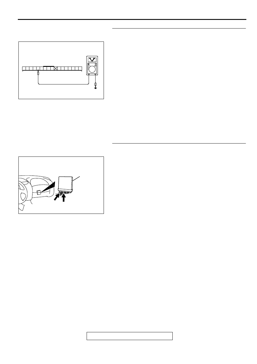
STEP 4. Check the power supply voltage at combination 
meter harness side connector C-41.
(1) Disconnect the connector C-41 and measure at the harness 

side.

(2) Turn the ignition switch to the "ON" position.
(3) Measure the voltage between terminal 52 and ground.

Voltage should be battery positive voltage.

(4)  Turn the ignition switch to the "LOCK" (OFF) position.

Q: Is the voltage normal?

YES : Go to Step 5.
NO :  Check harness connectors C-104 and C-101 at 

intermediate connector for damage, and repair or 
replace as required. Refer to GROUP 00E, Harness 
Connector Inspection (

P.00E-2

). If intermediate 

connectors are in good condition, repair harness wire 
between ignition switch connector C-87 terminal 2 
and combination meter connector C-41 terminal 52 
because of open circuit. Then confirm that the 
malfunction symptom is eliminated.

STEP 5. Check connector C-53 at ECM <M/T> or connector 
C-50 at PCM <A/T> for damage.
Q: Is the connector in good condition?

YES :  Go to Step 6.
NO :   Repair or replace it. Refer to GROUP 00E, Harness 

Connector Inspection (

P.00E-2

). Then confirm that 

the malfunction symptom is eliminated.

AK000364AC

56 55 54 53 52 5150 49 48

47 46 45 44 43 42 41

C-41 HARNESS
SIDE CONNECTOR

AK000280

C-50

C-53

ECM<M/T>
OR
PCM<A/T>

CONNECTORS:C-53<M/T>,C-50<A/T>

BK

MULTIPORT FUEL INJECTION (MFI) DIAGNOSIS

TSB Revision

MULTIPORT FUEL INJECTION (MFI) <2.4L ENGINE>

13A-348

STEP 6. Check the power supply voltage ECM connector 
C-53 <M/T> or PCM connector C-50 <A/T>.
(1) Disconnect the connector C-53 <M/T> or C-50 <A/T> and 

measure at the harness side.

(2) Turn the ignition switch to the "ON" position.
(3) Measure the voltage between terminal 36 <M/T> or 22 <A/

T> and ground.

 Voltage should be battery positive voltage.

(4) Turn the ignition switch to the "LOCK" (OFF) position.

Q: Is the voltage normal?

YES : Replace the ECM or PCM. Then confirm that the 

malfunction symptom is eliminated.

NO :  Check harness connectors C-28 at intermediate 

connector for damage, and repair or replace as 
required. Refer to GROUP 00E, Harness Connector 
Inspection (

P.00E-2

). If intermediate connectors is in 

good condition, repair harness wire between 
combination meter connector C-41 terminal 41 and 
ECM connector C-53 terminal 36 <M/T> or PCM 
connector C-50 terminal 22 <A/T> because of open 
circuit. Then confirm that the malfunction symptom is 
eliminated.

AK000381

<M/T>

C-53 HARNESS
SIDE CONNECTOR

AC

31

32

33

34

35

36

37

38

39

40

41

42

43

44

45

46

AK000377AD

1

2

3

4

5

6

7

8

9

10

11

12

13

14

15

16

17

18

19

20

21

22

23

24

25

26

27

28

29

30

31

32

33

34

35

<A/T>

C-50 HARNESS
SIDE CONNECTOR

MULTIPORT FUEL INJECTION (MFI) DIAGNOSIS

TSB Revision

MULTIPORT FUEL INJECTION (MFI) <2.4L ENGINE>

13A-349

INSPECTION PROCEDURE 4: The Service Engine Soon/Malfunction Indicator Lamp Remains 
Illuminated and Never Goes Out.

AK000675

44 45

41

46 47

42 43

49 50 5152

48

55 56

54

53

3

2

4 5 6

1 2 3
4 5 6

GREEN

1

RED-

YELLO

W

RED-

YELLO

W

BLA

CK-

WHITE

     C-104
(MU801457)

R

IG2

ST

LOCK

ACC

IG1

    C-101
MU801331

IGNITION
SWITCH

C-87

2

6

6

JUNCTION
BLOCK

52

C-41

41

C-28

SERVICE ENGINE SOON/
MALFUNCTION
INDICATOR LAMP

 C-53<M/T>
(MU803771)

 C-50<A/T>
(MU803784)

ENGINE CONTROL
MODULE(ECM)<M/T>
OR
POWERTRAIN CONTROL
MODULE(PCM)<A/T>

21

36<M/T>
22<A/T>

1

6

4

5

11

10

12 13

15

17

16

14

19

18

8 9

7

20

2 3

7 8

5

3 4

35

34

10 11 12

2122 23 24

13 14 15

25 26 27

16

28

17

18 19 20

29

30 31

32 33

36 37

38

9

1 2

6

34

33

32

36

35

37

42

45

31

39

38

46

40 41

43 44

2

3 4

5 6

7 8

9

11 12 13 14 15 16 17 18 19 20

30

21 22 23

24 25

26 27 28 29

3132 33

34 35

1

10

MULTIPORT FUEL INJECTION (MFI) DIAGNOSIS

TSB Revision

MULTIPORT FUEL INJECTION (MFI) <2.4L ENGINE>

13A-350

CIRCUIT OPERATION

The service engine soon/malfunction indicator 
lamp power is supplied from the ignition switch.

The ECM <M/T> or PCM <A/T> controls the 
ground of the service engine soon/malfunction 
indicator lamp by turning the power transistor in 
the ECM <M/T> or PCM <A/T> ON and OFF.

COMMENT

In cases such as the above, the cause is 
probably that the ECM <M/T> or PCM <A/T> is 
detecting a problem in a sensor or actuator, or 
that one of the malfunctions listed at right has 
probably occurred.

TROUBLESHOOTING HINTS (The most likely 
causes for this case:) 

Short-circuit between the service engine soon/
malfunction indicator lamp and ECM <M/T> or 
PCM <A/T>.

Malfunction of the ECM <M/T> or PCM <A/T>. 

DIAGNOSIS

Required Special Tool:
MB991502:Scan Tool (MUT-II)

AK000312AI

CONNECTOR:C-41

AK000280

C-50

C-53

ECM<M/T>
OR
PCM<A/T>

CONNECTORS:C-53<M/T>,C-50<A/T>

BK

AK000315

CONNECTOR:C-101

AC

AK000219

CONNECTOR:C-87

AC

AK000311

AK000311

CONNECTOR:C-104

AC

AK000733AC

CONNECTOR:C-28


Content   ..  160  161  162  163   ..