Mitsubishi Eclipse / Eclipse Spyder (2000-2002). Service and repair manual - part 160


  Index      Mitsubishi     Mitsubishi Eclipse / Eclipse Spyder (2000-2002). Service and repair manual


Search            


Content   ..  158  159  160  161   ..


Mitsubishi Eclipse / Eclipse Spyder (2000-2002). Service and repair manual - part 160


MULTIPORT FUEL INJECTION (MFI) DIAGNOSIS

TSB Revision

MULTIPORT FUEL INJECTION (MFI) <2.4L ENGINE>

13A-339

SYMPTOM PROCEDURES

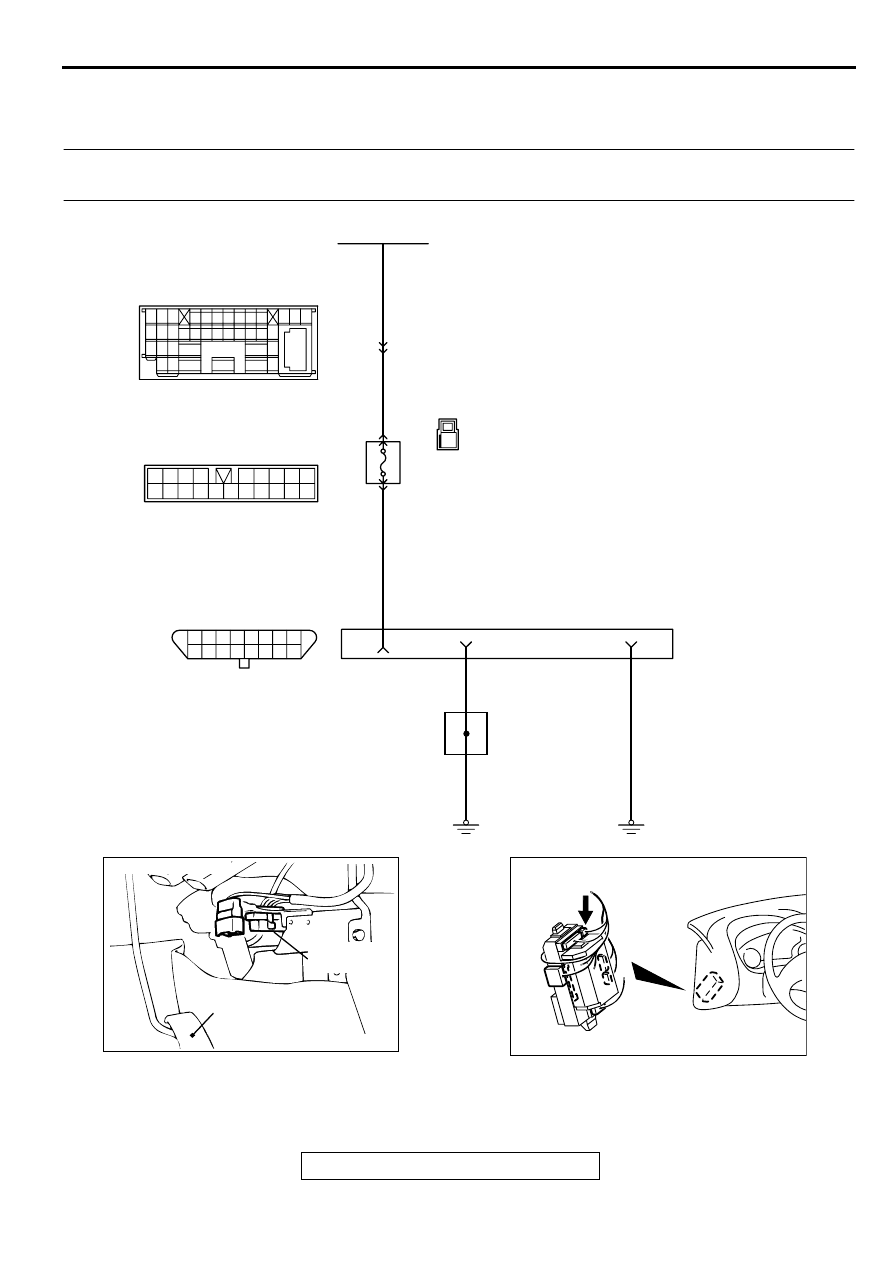
INSPECTION PROCEDURE 1: Communication with Scan Tool Is Not Possible. (Comunication with All 
Systems Is Not Possible.)

AK000673

15

14

13

12

11

10

1 2 3 4 5 6 7 8
9

16

1

1

6

4

5

11

10

12 13

15

17

16

14

19

18

8 9

7

20

2

15 16

26 27 28 29

32 33 34

17 18 19 20 21 22 23 24 25

30 31

36 37

35

38

10

11 12 13

1 2 3

4 5 6 7 8 9

14

3

RED

RED

RED-BLA

CK

BLA

CK

BLA

CK

BLA

CK

FUSIBLE LINK(2)

C-89

C-110

    C-104
MU801457

C-29

DATA LINK
CONNECTOR

38

1

18

16

JOINT
GROUND
POINT

4

5

JUNCTION
BLOCK

ACX02447

CONNECTOR:C-29

ACCELERATOR
PEDAL

DATA  LINK
CONNECTOR

AI

AK000355 AC

CONNECTOR:C-110

MULTIPORT FUEL INJECTION (MFI) DIAGNOSIS

TSB Revision

MULTIPORT FUEL INJECTION (MFI) <2.4L ENGINE>

13A-340

CIRCUIT OPERATION

A battery positive voltage is applied on the data 
link connector power terminal (terminal 16). The 
ground terminals (terminal 4, 5) are grounded to 
the vehicle body.

COMMENT

The cause is probably a defect in power supply 
system (including ground) for the on-board 
diagnostic test mode line.

TROUBLESHOOTING HINTS (The most likely 
causes for this case:) 

Malfunction of the data link connector.

Damaged harness wire.

DIAGNOSIS

STEP 1. Check the power supply voltage at data link 
connector C-29.
(1) Measure voltage between terminal 16 and ground.

Voltage should be battery positive voltage.

Q: Is the voltage normal?

YES : Go to step 2. 
NO :  Check harness connectors C-104, C-110 and C-89 at 

intermediate connector for damage, and repair or 
replace as required. Refer to GROUP 00E, Harness 
Connector Inspection (

P.00E-2

). If intermediate 

connectors are in good condition, repair harness wire 
between fusible link (2) and data link connector C-29 
terminal 16 because of open circuit. Then confirm that 
the malfunction symptom is eliminated.

STEP 2. Check the continuity at data link connector C-29.
(1) Check for the continuity between terminal 4, 5 and ground.

Should be less than 2 ohm.

Q: Is the continuity normal?

YES :  Replace the scan tool. Then confirm that the 

malfunction symptom is eliminated.

NO :  Repair harness wire between data link connector C-

29 terminal 4, 5 and ground because of open circuit or 
harness damage. Then confirm that the malfunction 
symptom is eliminated.

AK000311

AK000311

CONNECTOR:C-104

AC

AK000345AE

CONNECTOR:C-89

AKX01430AF

1 2 3 4 5 6 7 8
9 10 111213141516

C-29 HARNESS
SIDE CONECTOR

AKX01431AE

1 2 3 4 5 6 7 8
9 10 111213141516

C-29 HARNESS
SIDE CONECTOR

MULTIPORT FUEL INJECTION (MFI) DIAGNOSIS

TSB Revision

MULTIPORT FUEL INJECTION (MFI) <2.4L ENGINE>

13A-341

INSPECTION PROCEDURE 2: Communication with ECM or PCM Only Is Not Possible.

AK000674

58

60 61

53

52

51

55

54

56

59

62

57

GRA

Y

-

RED

GRA

Y

-

RED

GRA

Y

-

RED

RED-

WHITE

RED-

WHITE

RED-

WHITE

ENGINE CONTROL
MODULE(ECM)<M/T>
OR
POWERTRAIN CONTROL
MODULE(PCM)<A/T>

JOINT
CONNECTOR(1)

DATA LINK
CONNECTOR

 C-57<A/T>
(MU803782)

 C-56<M/T>
(MU803770)

C-28

C-77

C-29

56<M/T>
84<A/T>

62<M/T>
85<A/T>

1

11

8

9

10

12

15

7

98

78

71

88 89

76 77

72
79
91

73
80

74

75

81
92

8283
93

8485

94

8687

9596

90

97

7 8

5

3 4

35

34

10 11 12

2122 23 24

13 14 15

25 26 27

16

28

17

18 19 20

29

30 31

32 33

36 37

38

9

1 2

6

16

15

18

17

14

20

22

21

9

7

1 2

5

19

3

33

32

30 31

29

28

25

24

23

27

26

6

11

13

4

10

8

12

15

14

13

12

11

10

1 2 3 4 5 6 7 8
9

16

ACX02447

CONNECTOR:C-29

ACCELERATOR
PEDAL

DATA  LINK
CONNECTOR

AI

AK000312AH

CONNECTOR:C-77

MULTIPORT FUEL INJECTION (MFI) DIAGNOSIS

TSB Revision

MULTIPORT FUEL INJECTION (MFI) <2.4L ENGINE>

13A-342

CIRCUIT OPERATION

A diagnostic output is made from the ECM 
(terminal 62) <M/T> or PCM (terminal 85) <A/T> 
to the diagnostic output terminal (terminal 7) of 
the data link connector.

When diagnostic test mode control terminal 
(terminal 1) of the data link connector is 
grounded, the ECM (terminal 56) <M/T> PCM 
(terminal 84) <A/T> changes to the diagnostic 
test mode.

COMMENT

No power supply to ECM <M/T> or PCM <A/T>.

Defective ground circuit of ECM <M/T> or PCM 
<A/T>.

Defective ECM <M/T> or PCM <A/T>.

Improper communication line between ECM <M/
T> or PCM <A/T> and scan tool.

TROUBLESHOOTING HINTS (The most likely 
causes for this case:) 

Malfunction of ECM <M/T> or PCM <A/T> power 
supply circuit. 

Malfunction of the ECM <M/T> or PCM <A/T>. 

Open circuit between ECM <M/T> or PCM <A/T> 
and data link connector. 

DIAGNOSIS

STEP 1. Check connector C-56 at ECM <M/T> or connector 
C-57 at PCM <A/T> for damage.
Q: Is the connector in good condition?

YES :  Go to Step 2.
NO :  Repair or replace it. Refer to GROUP 00E, Harness 

Connector Inspection (

P.00E-2

). Then confirm that 

the malfunction symptom is eliminated.

AK000280

C-56,C-57

ECM<M/T>
OR
PCM<A/T>

CONNECTORS:C-56<M/T>,C-57<A/T>

BJ

AK000733AC

CONNECTOR:C-28

AK000280

C-56,C-57

ECM<M/T>
OR
PCM<A/T>

CONNECTORS:C-56<M/T>,C-57<A/T>

BJ


Content   ..  158  159  160  161   ..