Mitsubishi Eclipse / Eclipse Spyder (2000-2002). Service and repair manual - part 140


  Index      Mitsubishi     Mitsubishi Eclipse / Eclipse Spyder (2000-2002). Service and repair manual


Search            


Content   ..  138  139  140  141   ..


Mitsubishi Eclipse / Eclipse Spyder (2000-2002). Service and repair manual - part 140


MULTIPORT FUEL INJECTION (MFI) DIAGNOSIS

TSB Revision

MULTIPORT FUEL INJECTION (MFI) <2.4L ENGINE>

13A-259

STEP 14. Check the sensor power supply lines.
(1) Check all the sensor power supply lines for damage, which 

flow through the harness ECM connector (terminal 81) <M/
T> or PCM connector (terminal 46) <A/T>.

Q: Is there any failure in the sensor power supply lines?

When a failure is found : Repair if necessary. (Refer to 

GROUP 90, Circuit Diagrams 

 MFI System <M/T> 

P.90-36

<A/T

P.90-46

. Then go to Step 26.)

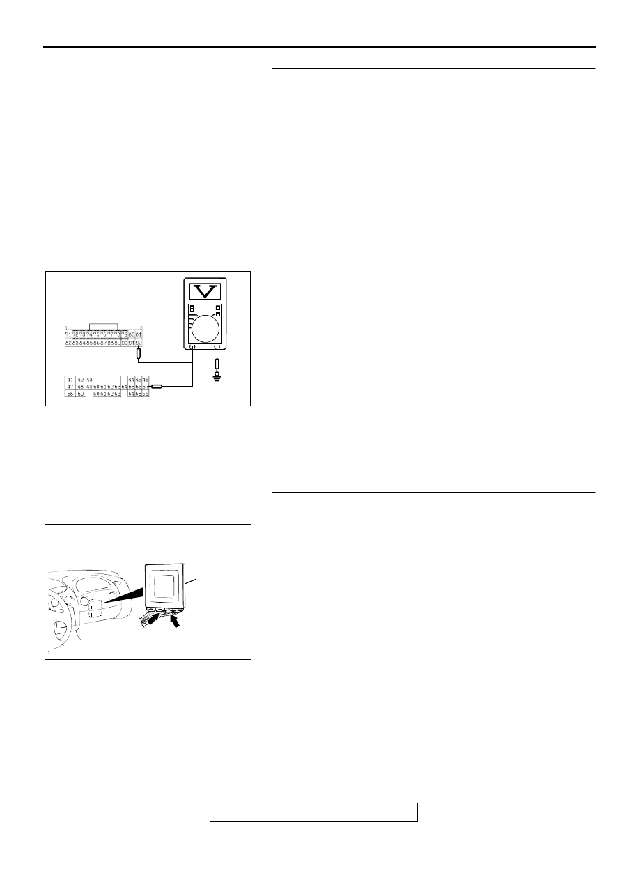
STEP 15. Check the ground circuit voltage at ECM 
connector C-60 <M/T> or PCM connector C-54 <A/T>.
(1) Do not disconnect ECM connector C-60 <M/T> or PCM 

connector C-54 <A/T>.

(2) Turn the ignition switch to the "ON" position.
(3) Measure the voltage between terminal 92 <M/T> or 57 <A/

T> and ground by backprobing.

Voltage should be 0.5 volts or less.

(4) Turn the ignition switch to the "LOCK" (OFF) position.

Q: Is the multi-meter reading below the specified value?

YES : Check connectors D-16, C-90, C-28, C-60 <M/T> or 

C-54 <A/T> and repair or replace as required. Refer 
to GROUP 00E, Harness Connector Inspection 

P.00E-2

. If connectors D-16, C-90, C-28, C-60 <M/T> 

or C-54 <A/T> are in good condition, check the 
harness between intermediate connector D-16 and 
ECM connector C-60 <M/T> or PCM connector C-54 
<A/T> for open circuit or damage. Then repair if 
necessary. Then go to Step 26.

NO :  Go to Step 16.

STEP 16. Check ECM connector C-60 <M/T> or PCM 
connector C-54 <A/T> for damage.
(1) Disconnect ECM connector C-60 <M/T> or PCM connector 

C-54 <A/T>. 

Q: Is there any failure at ECM connector C-60 <M/T> or 

PCM connector C-54 <A/T>?
YES : 
Repair or replace it. Refer to GROUP 00E, Harness 

Connector Inspection 

P.00E-2

. Then go to Step 26.

NO :  Go to Step 26.

AC002554 AC

<M/T> C-60

<A/T> C-54

HARNESS SIDE 
CONNECTOR

AC001689

CONNECTOR: C-60 <M/T>, C-54 <A/T>

ECM <M/T>
OR
PCM <A/T>

AL

C-54 
<A/T>

C-60 
<M/T>

MULTIPORT FUEL INJECTION (MFI) DIAGNOSIS

TSB Revision

MULTIPORT FUEL INJECTION (MFI) <2.4L ENGINE>

13A-260

STEP 17. Check the harness between fuel tank differential 
pressure sensor connector D-18 and intermediate 
connector D-16 for open circuit or damage.
(1) Disconnect fuel tank differential pressure sensor connector 

D-18 and intermediate connector D-16.

Q: Is there any failure between fuel tank differential 

pressure sensor connector D-18 and intermediate 
connector D-16?
YES : 
Repair it. Then go to Step 26.
NO :  Check connectors D-18, D-16 and repair or replace 

as required. Refer to GROUP 00e, Harness 
Connector Inspection 

P.00E-2

. Then go to Step 26.

STEP 18. Check ECM connector C-56 <M/T> or PCM 
connector C-57 <A/T> for damage.
(1) Disconnect ECM connector C-56 <M/T> or PCM connector 

C-57 <A/T>.

Q: Is there any failure at ECM connector C-56 <M/T> or 

PCM connector C-57 <A/T>?
YES : 
Go to Step 26.
NO :  Repair or replace it. Refer to GROUP 00e, Harness 

Connector Inspection 

P.00E-2

. Then go to Step 26.

AC002041AB

CONNECTOR: D-18

FUEL TANK DIFFERENTIAL 
PRESSURE SENSOR

AC002549 AB

CONNECTOR: D-16

INTERMEDIATE 
CONNECTOR

AC001689

CONNECTOR: C-56 <M/T>, C-57 <A/T>

ECM <M/T>
OR
PCM <A/T>

C-56 <M/T>, 
C-57 <A/T>

AM

MULTIPORT FUEL INJECTION (MFI) DIAGNOSIS

TSB Revision

MULTIPORT FUEL INJECTION (MFI) <2.4L ENGINE>

13A-261

STEP 19. Using scan tool MB991502, check data list item 
73: Fuel Tank Differential Pressure Sensor.

CAUTION

To prevent damage to scan tool MB991502, always turn the 
ignition switch to "LOCK" (OFF) position before 
connecting or disconnecting scan tool MB991502.
(1) Connect scan tool MB991502 to the data link connector.
(2) Turn the ignition switch to the "ON" position.
(3) Remove the fuel cap.
(4) Set scan tool MB991502 to the data reading mode for item 

73, Fuel Tank Differential Pressure Sensor.

The fuel tank pressures should be 

1.5 to 1.5kPa.

(5) Connect an evaporative emission system pressure pump to 

the fuel filler neck, and apply pressure.

The scan tool reading should increase.

Q: Is the scan tool reading within the specified value?

YES : Go to Step 26.
NO :  Replace the ECM or PCM. Then go to Step 26.

STEP 20. Check for clogging in the evaporator line from 
hose E to hose G.
(1) Remove the module bracket mounting bolts, and 

disconnect hose E from the evaporative emission 
ventilation solenoid side, and plug the hoses from which the 
hoses have been disconnected.

(2) Install the EVAP pressure pump outlet hose to the fuel tank 

filler neck as described in the pump manufacturer's 
instructions.

(3) On the EVAP pressure pump, set the pressure/hold valve to 

OPEN, and set the vent valve to CLOSED.

(4) Turn the pump timer to ON. You can reset the timer as 

required. (These settings are listed under "Leak Test" in the 
pump instructions.)

(5) When the hose E is unplugged, the air passes through the 

hose E.

Q: Does air pass through the hose E?

YES : Go to Step 21.
NO :  Go to Step 23.

AC001252

MB991502

16 PIN

AB

AC000186

AC002028

HOSE E

AC

OPEN

OPEN

CLOSED

CLOSED

Pressure
   Hold

Vent

ACX01806

MULTIPORT FUEL INJECTION (MFI) DIAGNOSIS

TSB Revision

MULTIPORT FUEL INJECTION (MFI) <2.4L ENGINE>

13A-262

STEP 21. Check the vent valve module for clogging.
(1) Check the vent valve module for clogging. (Refer to 

GROUP 17 

 Vent Valve 

P.17-103

.)

Q: Air there any clogs?

YES : Replace the vent valve module. Then go to Step 26.
NO :  Go to Step 22.

STEP 22. Check for clogging in the evaporator lines O and 
hose   P.
(1) Apply vacuum with a hand vacuum pump connected to 

hose O and hose P.

Q: Are there any clogs?

YES : Replace that hose. Then go to Step 26.
NO :  Go to Step 26.

STEP 23. Check for clogging in the evaporator line from 
hose G.
(1) Carry out the clogging test with a hand vacuum pump on 

each hose from hose G.

Q: Are there any clogs?

YES : Replace that hose. Then go to Step 26.
NO :  Go to Step 24.

AC002034 AB

AC002033 AE

HOSE P

HOSE O

AC002072

HOSE G

AD


Content   ..  138  139  140  141   ..