Mitsubishi Eclipse / Eclipse Spyder (2000-2002). Service and repair manual - part 126


  Index      Mitsubishi     Mitsubishi Eclipse / Eclipse Spyder (2000-2002). Service and repair manual


Search            


Content   ..  124  125  126  127   ..


Mitsubishi Eclipse / Eclipse Spyder (2000-2002). Service and repair manual - part 126


MULTIPORT FUEL INJECTION (MFI) DIAGNOSIS

TSB Revision

MULTIPORT FUEL INJECTION (MFI) <2.4L ENGINE>

13A-203

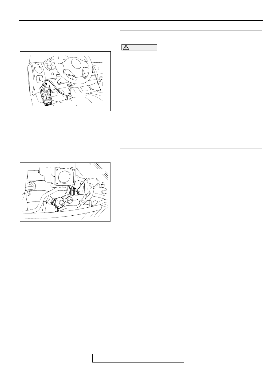
STEP 1. Using scan tool MB991502, check actuator test 
item 10: EGR solenoid.

CAUTION

To prevent damage to scan tool MB991502, always turn the 
ignition switch to the "LOCK" (OFF) position before 
connecting or disconnecting scan tool MB991502.
(1) Connect scan tool MB991502 to the data link connector.
(2) Turn the ignition switch to the "ON" position.
(3) Set scan tool MB991502 to the actuator test mode for item 

10, EGR solenoid.

An operation sound should be heard and vibration 
should be felt when the EGR solenoid is operated.

(4) Turn the ignition switch to the "LOCK" (OFF) position.

Q: Is the solenoid operating properly?

YES : It can be assumed that this malfunction is intermittent. 

Refer to GROUP 00, How to Use Troubleshooting/
Inspection Service Points (

P.00-6

).

NO :  Go to Step 2.

STEP 2. Check connector B-31 at the EGR solenoid for 
damage.
Q: Is the connector in good condition?

YES : Go to Step 3.
NO :  Repair or replace it. Refer to GROUP 00E, Harness 

Connector Inspection (

P.00E-2

). Then go to Step 12.

AKX01177

16 PIN

MB991502

AB

ACX02513

EGR
SOLENOID
VALVE

CONNECTOR:B-31

AI

MULTIPORT FUEL INJECTION (MFI) DIAGNOSIS

TSB Revision

MULTIPORT FUEL INJECTION (MFI) <2.4L ENGINE>

13A-204

STEP 3 Check the EGR solenoid.
(1) Disconnect the EGR solenoid connector B-31.
(2) Measure the resistance between EGR solenoid side 

connector terminal 1 and 2.

   Standard value: 29 

 35

 [at 20

°

 C (68

°

 F)]

Q: Is the resistance at the standard value?

YES : Go to Step 4.
NO :  Replace the EGR solenoid. Then go to Step 12.

STEP 4. Check the power supply voltage at EGR solenoid 
harness side connector B-31.
(1) Disconnect the connector B-31 and measure at the harness 

side.

(2) Turn the ignition switch to the "ON" position.
(3) Measure the voltage between terminal 1 and ground.

Voltage should be battery positive voltage

(4) Turn the ignition switch to the "LOCK" (OFF) position.

Q: Is the voltage normal?

YES : Go to Step 6.
NO :  Go to Step 5.

STEP 5. Check connector A-21X at MFI relay for damage.
Q: Is the connector in good condition?

YES : Check connector B-13 at intermediate connector for 

damage, and repair or replace as required. Refer to 
GROUP 00E, Harness Connector Inspection (

P.00E-

2

). If intermediate connectors is in good condition, 

repair harness wire between MFI relay connector A-
21X terminal 1 and EGR solenoid connector B-31 
terminal 1 because of open circuit or short circuit to 
ground. Then go to Step 12.

NO :  Repair or replace it. Refer to GROUP 00E, Harness 

Connector Inspection (

P.00E-2

). Then go to Step 12.

ACX02513

EGR
SOLENOID
VALVE

CONNECTOR:B-31

AI

AKX00352

AK000254 AE

B-31 HARNESS
SIDE CONNECTOR

1

2

AK000226

AK000226AB

CONNECTOR : A-21X

MFI RELAY

MULTIPORT FUEL INJECTION (MFI) DIAGNOSIS

TSB Revision

MULTIPORT FUEL INJECTION (MFI) <2.4L ENGINE>

13A-205

STEP 6. Check the power supply voltage at ECM connector 
C-49 <M/T> or PCM connector C-50 <A/T> by backprobing
(1) Do not disconnect the connector C-49 <M/T> or C-50 <A/

T>.

(2) Turn the ignition switch to the "ON" position.
(3) Measure the voltage between terminal 6 and ground by 

backprobing.

Voltage should be battery positive voltage.

(4) Turn the ignition switch to the "LOCK" (OFF) position.

Q: Is the voltage normal?

YES : Go to Step 9.
NO :  Go to Step 7.

STEP 7. Check connector C-49 at ECM <M/T> or connector 
C-50 at PCM <A/T> for damage.
Q: Is the connector in good condition?

YES : Go to Step 8.
NO :  Repair or replace it. Refer to GROUP 00E, Harness 

Connector Inspection (

P.00E-2

). Then go to Step 12.

AK000298

10

1 2 3 4 5 6 7 8 9

1112 13

141516171819 20 2122 23242526

AC

<M/T>

C-49 CONNECTOR
HARNESS SIDE VIEW

AK000299

1

2

3 4

5 6

7 8

9 10 11 1213 141516 17 1819 20 21 2223

24 25

2627 2829

30 3132 33

3435

AD

C-50 CONNECTOR
HARNESS SIDE VIEW

<A/T>

AK000280

C-49,C-50

ECM<M/T>
OR
PCM<A/T>

CONNECTORS:C-49<M/T>,C-50<A/T>

BC

MULTIPORT FUEL INJECTION (MFI) DIAGNOSIS

TSB Revision

MULTIPORT FUEL INJECTION (MFI) <2.4L ENGINE>

13A-206

STEP 8. Check for open circuit and short circuit to ground 
between EGR solenoid connector B-31 terminal 2 and ECM 
connector C-49 terminal 6 <M/T> or PCM connector C-50 
terminal 6 <A/T>.
NOTE: Check harness after checking intermediate connector 
B-13.If intermediate connectors is damaged, repair or replace 
them.Refer to GROUP 00E, Harness Connector Inspection 
(

P.00E-2

). Then go to Step 12.

Q: Is the harness wire in good condition?

YES : Replace the ECM or PCM. Then go to Step 12.
NO :  Repair it. Then go to Step 12.

STEP 9. Check connector C-49 at ECM <M/T> or connector 
C-50 at PCM <A/T> for damage.
Q: Is the connector in good condition?

YES : Go to Step 10.
NO :  Repair or replace it. Refer to GROUP 00E, Harness 

Connector Inspection (

P.00E-2

). Then go to Step 12.

ACX02513

EGR
SOLENOID
VALVE

CONNECTOR:B-31

AI

AK000280

C-49,C-50

ECM<M/T>
OR
PCM<A/T>

CONNECTORS:C-49<M/T>,C-50<A/T>

BC

AK000280

C-49,C-50

ECM<M/T>
OR
PCM<A/T>

CONNECTORS:C-49<M/T>,C-50<A/T>

BC


Content   ..  124  125  126  127   ..