Mitsubishi Eclipse. Manual - part 984
AERO PARTS
TSB Revision
EXTERIOR
51-13
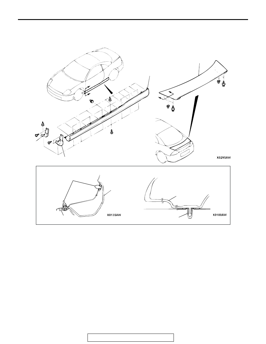
AERO PARTS
REMOVAL AND INSTALLATION
M1511005000039
REMOVAL STEPS
1. STONE GUARD <VEHICLES
WITHOUT SIDE AIR DAM>
2. FRONT SIDE AIR DAM
3. REAR SIDE AIR DAM
4. REAR SPOILER
AC003621
SECTION A – A
SECTION B – B
A
A
B
B
1
2
3
4
2
3
4
CLIP
CLIP
AB