Mitsubishi Eclipse. Manual - part 794


  Index      Mitsubishi     Mitsubishi Eclipse - service repair manual 2004 year


Search            


Content   ..  792  793  794  795   ..


Mitsubishi Eclipse. Manual - part 794


AUTOMATIC TRANSAXLE DIAGNOSIS

TSB Revision

AUTOMATIC TRANSAXLE

23A-185

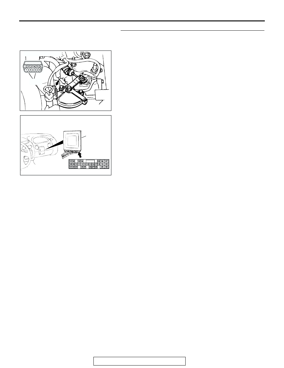
STEP 40. Check harness for open circuit or short circuit to 
ground between transmission range switch connector 
B-41 terminal 5 and PCM connector C-61 terminal 109.
Q: Is the harness wire in good condition?

YES : Go to Step 5.
NO :  Repair or replace the harness wire.

AC001844

CONNECTOR: B-41

DIPSTICK

AK

B-41

AC001657

CONNECTOR: C-61

PCM

BH

C-61

AUTOMATIC TRANSAXLE DIAGNOSIS

TSB Revision

AUTOMATIC TRANSAXLE

23A-186

STEP 41. Check the transmission range switch.
Measure the resistance between the terminals for each selec-
tor position as indicated in the table below.

NOTE: For vehicles with sport mode, four positions (P, R, N, D) 
are used.
Q: Is the measured resistance less than 2 ohms for each 

selector position?
YES : 
Go to Step 42.
NO :  Replace the transmission range switch. Refer to 

GROUP 23B, Transaxle 

P.23B-10

.

STEP 42. Check transmission range switch connector B-41 
for loose, corroded or damaged terminals, or terminals 
pushed back in the connector.
Q: Are the connector and terminals in good condition?

YES : Go to Step 43.
NO :  Repair or replace the damaged components. Refer to 

GROUP 00E, Harness Connector Inspection 

P.00E-2

.

SELECTOR 
POSITION

TERMINAL CONNECTION 
OF TESTER

SPECIFIED 
CONDITION

P

− 8, 9 − 10

Less than 2 ohms.

R

− 8

N

− 8, 9 − 10

D

− 8

3

− 8

2

− 8

L

− 8

AC004672

DIPSTICK

TRANSMISSION
RANGE SWITCH

AK

AC005865

P

R

N

D

3

2

L

AB

AC001844

CONNECTOR: B-41

DIPSTICK

AK

B-41

AUTOMATIC TRANSAXLE DIAGNOSIS

TSB Revision

AUTOMATIC TRANSAXLE

23A-187

STEP 43. Measure the transmission range switch output 
voltage at PCM connector C-61 by backprobing.
(1) Do not disconnect connector C-61.
(2) Turn the ignition switch to the "ON" position.
(3) Move the selector lever to the "2" position.

(4) Measure the voltage between terminal 122 and ground by 

backprobing.

• The voltage should measure battery positive voltage.

(5) Turn the ignition switch to the "LOCK" (OFF) position.
Q: Does the voltage measure battery positive voltage?

YES : Go to Step 13.
NO :  Go to Step 44.

STEP 44. Check PCM connector C-61 for loose, corroded 
or damaged terminals, or terminals pushed back in the 
connector.
Q: Are the connector and terminals in good condition?

YES : Go to Step 45.
NO :  Repair or replace the damaged components. Refer to 

GROUP 00E, Harness Connector Inspection 

P.00E-2

.

AC001657

CONNECTOR: C-61

PCM

BH

C-61

AC001908AM

C-61 HARNESS 
CONNECTOR:
HARNESS SIDE

AC001657

CONNECTOR: C-61

PCM

BH

C-61

AUTOMATIC TRANSAXLE DIAGNOSIS

TSB Revision

AUTOMATIC TRANSAXLE

23A-188

STEP 45. Check harness for open circuit or short circuit to 
ground between transmission range switch connector 
B-41 terminal 2 and PCM connector C-61 terminal 122.
Q: Is the harness wire in good condition?

YES : Go to Step 5.
NO :  Repair or replace the harness wire.

AC001844

CONNECTOR: B-41

DIPSTICK

AK

B-41

AC001657

CONNECTOR: C-61

PCM

BH

C-61


Content   ..  792  793  794  795   ..