Mitsubishi Eclipse. Manual - part 730


  Index      Mitsubishi     Mitsubishi Eclipse - service repair manual 2004 year


Search            


Content   ..  728  729  730  731   ..


Mitsubishi Eclipse. Manual - part 730


MAINTENANCE SERVICE

TSB Revision

GENERAL

00-63

SRS COMPONENT VISUAL CHECK

DANGER

Wait at least 60 seconds after disconnecting the bat-
tery cable before doing any further work. The SRS 
system is designed to retain enough voltage to 
deploy the air bag for a short time even after the bat-
tery has been disconnected, Serious injury may result 
from unintended air bag deployment if work is done 
on the SRS system immediately after the battery 
cable is disconnected.

WARNING

Battery posts, terminals and related accessories con-
tain lead and lead compounds. WASH HANDS AFTER 
HANDLING.

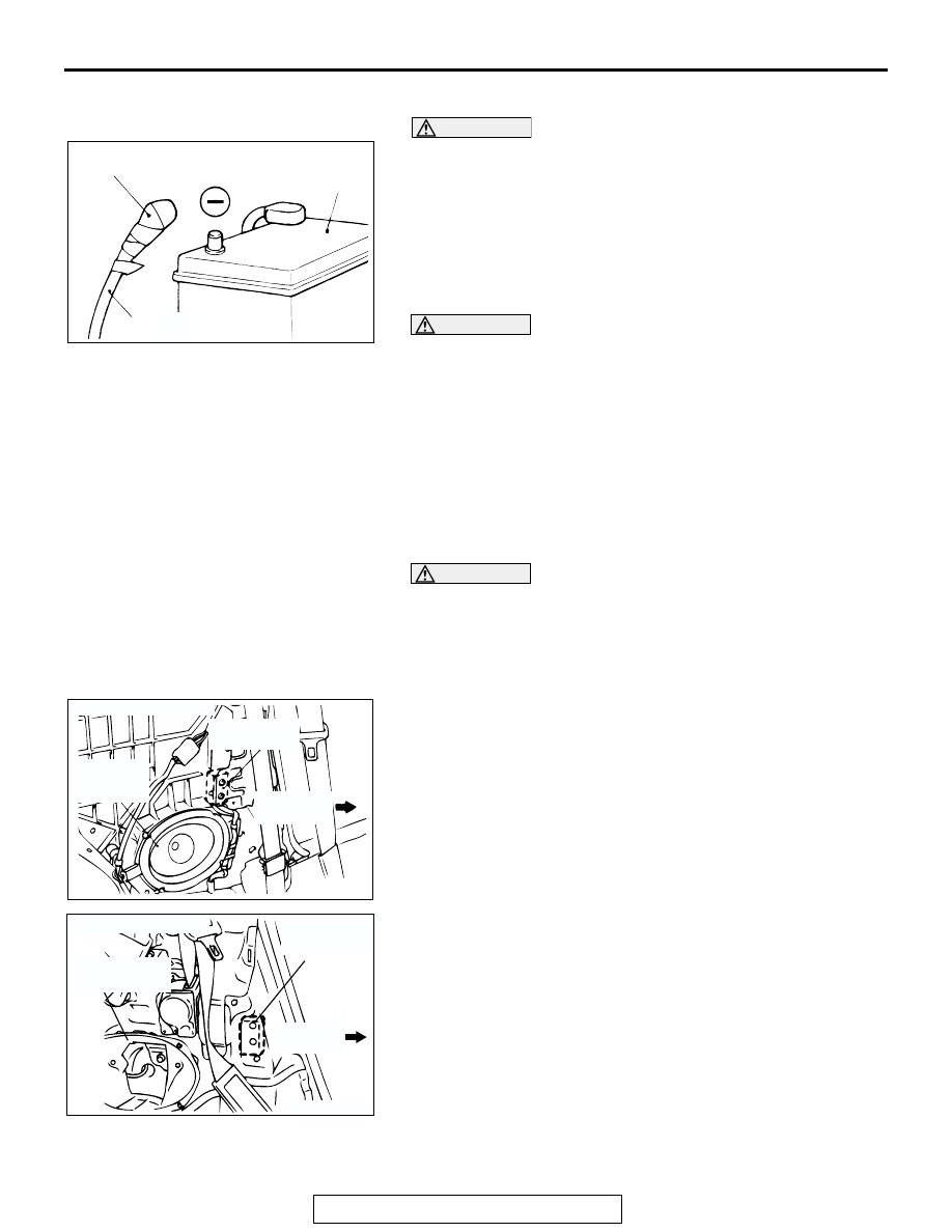
1. Turn the ignition switch to the "LOCK" (OFF) position, 

disconnect the negative battery cable and tape the terminal.

2. Remove the floor console assembly. (Refer to GROUP 52A, 

Floor Console Assembly 

P.52A-7

.)

3. Disconnect a connector from the SRS-ECU.

SIDE IMPACT SENSORS

WARNING

If the side impact sensor is not installed securely 
and correctly, the side-airbag may not operate nor-
mally.

If a dent, crack, deformation or rust is detected, 
replace with a new sensor.

1. Check the side impact sensor and bracket for dents, cracks 

or deformation.

2. Check the connector for damage, and terminal for 

deformation.

3. Check that there is no bending or corrosion in the side outer 

panel (ECLIPSE) or quarter panel (ECLIPSE SPYDER).

ACX00902 AB

TAPE

BATTERY

BATTERY CABLE

AC000113

REAR
SPEAKER
(LH)

SIDE IMPACT
SENSOR

FRONT OF
VEHICLE

AC

< ECLIPSE >

AC002718AB

FRONT
VEHICLE

SIDE IMPACT
SENSOR

REAR
SPEAKER(LH)

<ECLIPSE SPYDER>

MAINTENANCE SERVICE

TSB Revision

GENERAL

00-64

REPLACE THE SIDE IMPACT SENSOR IF IT FALS 
THE VISUAL CHECK

Refer to GROUP 52B,Side Impact Sensor 

P.52B-156

.

NOTE: The illustration at left shows the left side impact sensor 
(LH). The position of the side impact sensor (RH) is symmetri-
cal to this.

SRS AIR BAG CONTROL UNIT (SRS-ECU)

WARNING

The SRS may not activate if the SRS-ECU (with 
built-in safing G-sensor and analog G-sensor) is not 
installed properly, which could result in serious injury 
or death to the vehicle's driver and passenger.

1. Check the SRS-ECU case and brackets for dents, cracks, 

deformation or rust.

2. Check the connector for damage, and check the terminals 

for deformation or rust.
Replace the SRS-ECU if it fails the visual checks above. 
(Refer to GROUP 52B, SRS Control Unit 

P.52B-144

.)

AIR BAG MODULE, STEERING WHEEL AND 
CLOCK SPRING

WARNING

The removed air bag module should be stored in a 
clean, dry place with the pad cover face up.

1. Remove the air bag module, steering wheel and clock 

spring.
(Refer to GROUP 52B, Air Bag Module and Clock Spring 

P.52B-146

.)

2. Check the pad cover for dents, cracks or deformation.

AC000114AB

CENTER REINFORCEMENT (RH)

SRS-ECU

MAINTENANCE SERVICE

TSB Revision

GENERAL

00-65

3. Check the connector for damage and deformed terminals, 

and check the harness for binds.

4. Check the air bag inflator case for dents, cracks or 

deformation.

5. Check the harness (built into the steering wheel) and 

connectors for damage, and check the terminals for 
deformation.

6. Check the clock spring connectors and protective tube for 

damage, and terminals for deformities.

7. Visually check the case for damage.

WARNING

If the clock spring's mating mark is not properly 
aligned, the steering wheel may not completely rotate 
during a turn, or the flat cable within the clock spring 
may be severed, obstructing normal operation of the 
SRS and possibly leading to serious injury to the 
vehicle's driver and front passenger.

8. Align the mating marks of the clock spring, and after turning 

the front wheels to the straight-ahead position, install the 
clock spring to the column.

     Mating marks alignment
     After turning the clock spring fully clockwise, turn it approxi-

mately 3 4/5 turns counterclockwise until the mating marks 
are aligned.

AC000116

<DRIVER'S SIDE>

<FRONT PASSENGER'S SIDE>

AB

INFLATOR CASE

CONNECTOR

COVER

INFLATOR
CASE

CONNECTOR

ACX01302

CASE

PROTECTIVE
TUBES

AB

ACX00602 AB

MATING MARK

MAINTENANCE SERVICE

TSB Revision

GENERAL

00-66

9. Install the steering column covers, steering wheel and air 

bag module.

10.Check the steering wheel for noise, binds or difficult 

operation.

DANGER

The SRS may not activate if any of the above compo-
nents are not installed properly, which could result in 
serious injury or death to the vehicle's driver and 
front passenger.

11.Check the steering wheel for excessive free play.

REPLACE ANY PART IF IT FAILS VISUAL INSPECTION. 
(Refer to GROUP 52B, Air Bag Module and Clock Spring 

P.52B-146

.)

FRONT SEATBACK ASSEMBLY WITH 
SIDE-AIRBAG MODULE

WARNING

If any improper part is found during the following 
inspection, replace the front seatback assembly 
with a new one.

Dispose of the old one according to the specified 
procedure. (Refer to GROUP 52B, Air Bag Module 
Disposal Procedures 

P.52B-160

.)

Never attempt to measure the circuit resistance of 
the air bag module (squib) even if you are using 
the specified tester. If the circuit resistance is mea-
sured with a tester, accidental air bag deployment 
will result in serious personal injury.

1. Check the air bag module deployment section for dents or 

deformation.

2. Check the connector for damage, the terminals for 

deformation, and harness for binds.

AC000118

AIR
BAG MODULE

AB

AC002988AB

AIR BAG MODULE
DEPLOYMENT
SECTION


Content   ..  728  729  730  731   ..