Mitsubishi Eclipse. Manual - part 695


  Index      Mitsubishi     Mitsubishi Eclipse - service repair manual 2004 year


Search            


Content   ..  693  694  695  696   ..


Mitsubishi Eclipse. Manual - part 695


AUTO-CRUISE CONTROL

TSB Revision

ENGINE AND EMISSION CONTROL

17-61

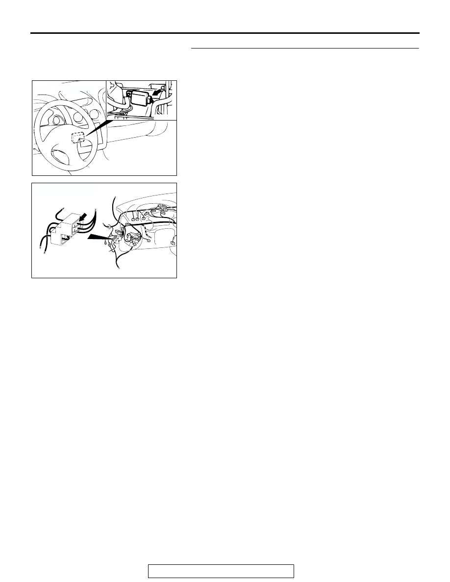
STEP 10. Check the harness wire between intermediate 
connector C-89 (terminal number 14) and auto-cruise 
control-ECU connector C-20 (terminal number 4).
Q: Is any harness wire between intermediate connector 

C-89 (terminal number 14) and auto-cruise control-ECU 
connector C-20 (terminal number 4) damaged?
YES : 
Repair the harness wire and then check that the 

malfunction is eliminated.

NO :  Check that the malfunction is eliminated. If the 

malfunction is not eliminated, replace the auto-cruise 
control-ECU (Refer to 

P.17-92

.). Then check that the 

malfunction is eliminated.

AC001451

CONNECTOR: C-20

AB

AC103104AD

CONNECTOR: C-89

CONNECTOR 
BLOCK (LH)

AUTO-CRUISE CONTROL

TSB Revision

ENGINE AND EMISSION CONTROL

17-62

INSPECTION PROCEDURE 3: When the Clutch Pedal is Depressed, Auto-cruise Control is not 
Cancelled. <M/T>

AC005115

Clutch Pedal Position Switch Circuit

AB

AC101196AF

CONNECTOR: C-01

AC001451

CONNECTOR: C-20

AB

AUTO-CRUISE CONTROL

TSB Revision

ENGINE AND EMISSION CONTROL

17-63

.

CIRCUIT OPERATION
This circuit indicates the operation status of the 
clutch pedal position switch. When the clutch pedal 
position switch is ON (clutch pedal is depressed), the 
voltage of auto-cruise control-ECU terminal number 
13 will indicate 0 volt.

.

TECHNICAL DESCRIPTION (COMMENT)
The cause is probably a malfunction of the clutch 
pedal position switch circuit.

.

TROUBLESHOOTING HINTS

• Malfunction of the clutch pedal position switch.

• Damaged harness or connector.

• Malfunction of the auto-cruise control-ECU.

DIAGNOSIS

STEP 1. Check the clutch pedal position switch.
1.Disconnect clutch pedal position switch connector C-01.
2.Measure the continuity between the terminals.

Q: Is the continuity meet the table above?

YES : Go to Step 2.
NO :  Replace the clutch pedal position switch. Refer to 

GROUP 21A, Clutch 

P.21A-10

. Then check that the 

malfunction is eliminated.

AC103104AD

CONNECTOR: C-89

CONNECTOR 
BLOCK (LH)

MEASUREMENT 
CONDITION

TERMINAL 
CONNECTOR 
OF TESTER

SPECIFIED 
CONDITION

When clutch pedal is 
depressed. 

− 2

Less than 2 
ohms

When clutch pedal is not 
depressed.

− 2

Open circuit

ACX02256AF

CLUTCH PEDAL POSITION
SWITCH CONNECTOR: C-01

AUTO-CRUISE CONTROL

TSB Revision

ENGINE AND EMISSION CONTROL

17-64

STEP 2. Check the output circuit voltage at auto-cruise 
control-ECU connector C-20 (terminal number 13) by 
backprobing.
(1) Do not disconnect auto-cruise control switch connector 

C-20.

(2) Turn the ignition switch to the "ON" position.
(3) Measure the voltage between terminal 13 and ground by 

backprobing.

• Voltage should be 0.5 volt or less. (When clutch pedal is 

depressed.)

• Voltage should be battery positive voltage. (When clutch 

pedal is not depressed.)

(4) Turn the ignition switch to the "LOCK" (OFF) position.
Q: Is the voltage within specifications?

YES : Check that the malfunction is eliminated. If the 

malfunction is not eliminated, replace the auto-cruise 
control-ECU (Refer to 

P.17-92

.). Then check that the 

malfunction is eliminated.

NO :  Go to Step 3.

1 2 3 4 5 6 7 8

9 10 11 12 13 14 15 16

AC103109

C-20 CONNECTOR
HARNESS SIDE VIEW

AC


Content   ..  693  694  695  696   ..