Mitsubishi Eclipse. Manual - part 623


  Index      Mitsubishi     Mitsubishi Eclipse - service repair manual 2004 year


Search            


Content   ..  621  622  623  624   ..


Mitsubishi Eclipse. Manual - part 623


MULTIPORT FUEL INJECTION (MFI) DIAGNOSIS

TSB Revision

MULTIPORT FUEL INJECTION (MFI) <3.0L>

13B-1035

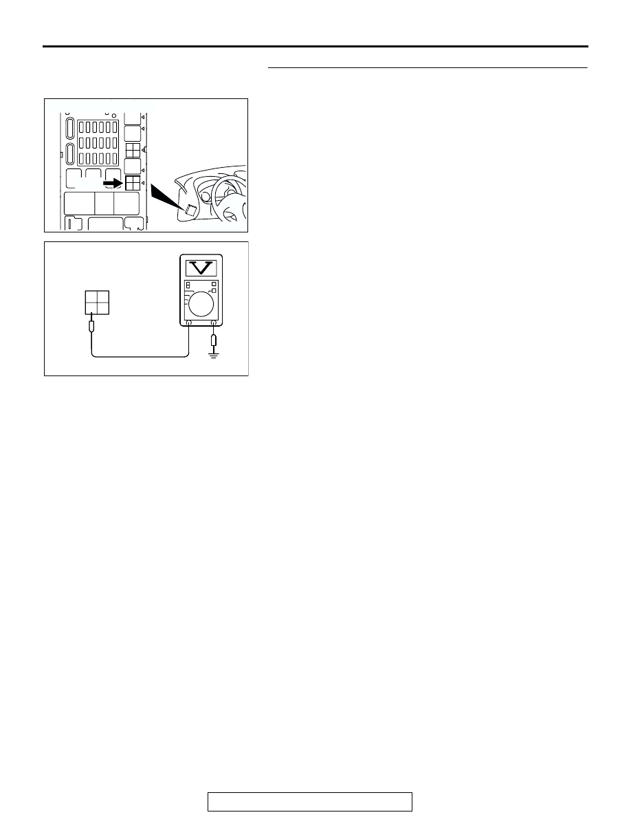
STEP 4. Check the power supply voltage at fuel pump relay 
1 harness side connector C-107.
(1) Disconnect the connector C-107 and measure at the 

harness side.

(2) Measure the voltage between terminal 4 and ground.

• Voltage should be battery positive voltage.

Q: Is battery positive voltage (approximately 12 volts) 

present?
YES : 
Go to Step 5.
NO :  Check harness connectors C-89 and C-112 at 

intermediate connector for damage, and repair or 
replace as required. Refer to, GROUP 00E, Harness 
Connector Inspection 

P.00E-2

. If intermediate 

connectors are in good condition, repair harness wire 
between dedicated fuse and fuel pump relay 1 
connector C-107 terminal 4 because of open circuit. 
Then confirm that the malfunction symptom is 
eliminated.

3

4

1

2

3

4

1

2

3

4

1

2

3

4

1

2

3

4

1

2

3

4

1

2

3

4

1

2

AK300745

CONNECTOR: C-107

AB

C-107

AK103736

1

2

3

4

1

2

3

4

AJ

C-107 HARNESS 
CONNECTOR: 
COMPONENT SIDE

MULTIPORT FUEL INJECTION (MFI) DIAGNOSIS

TSB Revision

MULTIPORT FUEL INJECTION (MFI) <3.0L>

13B-1036

STEP 5. Check the power supply voltage at fuel pump relay 
1 harness side connector C-107.
(1) Disconnect the connector C-107 and measure at the 

harness side.

(2) Turn the ignition switch to the "ON" position.

(3) Measure the voltage between terminal 3 and ground.

• Voltage should be battery positive voltage.

(4) Turn the ignition switch to the "LOCK" (OFF) position.
Q: Is battery positive voltage (approximately 12 volts) 

present?
YES : 
Go to Step 6.
NO :  Check harness connector C-111 at intermediate 

connector for damage, and repair or replace as 
required. Refer to, GROUP 00E, Harness Connector 
Inspection 

P.00E-2

If intermediate connector is in 

good condition, repair harness wire between ignition 
switch connector C-87 terminal 2 and fuel pump relay 
1 connector C-107 terminal 3 because of open circuit. 
Then confirm that the malfunction symptom is 
eliminated.

3

4

1

2

3

4

1

2

3

4

1

2

3

4

1

2

3

4

1

2

3

4

1

2

3

4

1

2

AK300745

CONNECTOR: C-107

AB

C-107

AK101347

1

2

3

4

AU

C-107 HARNESS 
CONNECTOR: 
COMPONENT SIDE

MULTIPORT FUEL INJECTION (MFI) DIAGNOSIS

TSB Revision

MULTIPORT FUEL INJECTION (MFI) <3.0L>

13B-1037

STEP 6. Check the continuity at fuel pump relay 1 harness 
side connector C-107.
(1) Disconnect the connector C-107 and measure at the 

harness side.

(2) Check for the continuity between terminal 2 and ground.

• Should be less than 2 ohms.

Q: Is the continuity normal?

YES : Go to Step 7.
NO :  Check harness connectors C-108 at intermediate 

connector for damage, and repair or replace as 
required. Refer to, GROUP 00E, Harness Connector 
Inspection 

P.00E-2

If intermediate connectors are in 

good condition, repair harness wire between fuel 
pump relay 1 connector C-107 terminal 2 and ground 
because of open circuit. Then confirm that the 
malfunction symptom is eliminated.

STEP 7. Check the power supply voltage at fuel pump relay 
2 harness side connector C-105.
(1) Disconnect the connector C-105 and measure at the 

harness side.

(2) Turn the ignition switch to the "ON" position.

(3) Measure the voltage between terminal 1 and ground.

• Voltage should be battery positive voltage.

Q: Is battery positive voltage (approximately 12 volts) 

present?
YES : 
Go to Step 8.
NO :  Repair harness wire between fuel pump relay 1 

connector C-107 terminal No. 1 and fuel pump relay 2 
connector C-105 terminal No. 1 because of open 
circuit. Then confirm that the malfunction symptom is 
eliminated.

3

4

1

2

3

4

1

2

3

4

1

2

3

4

1

2

3

4

1

2

3

4

1

2

3

4

1

2

AK300745

CONNECTOR: C-107

AB

C-107

AK103839

1

2

3

4

1

2

3

4

AH

C-107 HARNESS 
CONNECTOR: 
COMPONENT SIDE

3

4

1

2

3

4

1

2

3

4

1

2

3

4

1

2

3

4

1

2

3

4

1

2

3

4

1

2

AK300746

CONNECTOR: C-105

AB

C-105

AK101349

1

2

3

4

AR

C-105 HARNESS 
CONNECTOR: 
COMPONENT SIDE

MULTIPORT FUEL INJECTION (MFI) DIAGNOSIS

TSB Revision

MULTIPORT FUEL INJECTION (MFI) <3.0L>

13B-1038

STEP 8. Check the power supply voltage at fuel pump relay 
2 harness side connector C-105.
(1) Disconnect the connector C-105 and measure at the 

harness side.

(2) Turn the ignition switch to the "ON" position.

(3) Measure the voltage between terminal No. 3 and ground.

• Voltage should be battery positive voltage.

(4) Turn the ignition switch to the "LOCK" (OFF) position.
Q: Is the voltage normal?

YES : Go to Step 9.
NO :  Check harness connector C-111 at intermediate 

connector for damage, and repair or replace as 
required. Refer to, GROUP 00E, Harness Connector 
Inspection 

P.00E-2

If intermediate connector is in 

good condition, repair harness wire between ignition 
switch connector C-87 (terminal No. 2) and fuel pump 
relay 2 connector C-105 (terminal No. 3) because of 
open circuit. Then confirm that the malfunction 
symptom is eliminated.

STEP 9. Check connector D-17 at fuel pump for damage.
Q: Is the connector in good condition?

YES : Go to Step 10.
NO :  Repair or replace it. Refer to GROUP 00E, Harness 

Connector Inspection 

P.00E-2

. Then confirm that the 

malfunction symptom is eliminated.

3

4

1

2

3

4

1

2

3

4

1

2

3

4

1

2

3

4

1

2

3

4

1

2

3

4

1

2

AK300746

CONNECTOR: C-105

AB

C-105

AK101347

1

2

3

4

AV

C-105 HARNESS 
CONNECTOR: 
COMPONENT SIDE

AK300446

1

2

3

4

5

D-17 (GR)

AB

CONNECTOR: D-17

HARNESS CONNECTOR:
COMPONENT SIDE


Content   ..  621  622  623  624   ..