Mitsubishi Eclipse. Manual - part 622
MULTIPORT FUEL INJECTION (MFI) DIAGNOSIS
TSB Revision
MULTIPORT FUEL INJECTION (MFI) <3.0L>
13B-1031
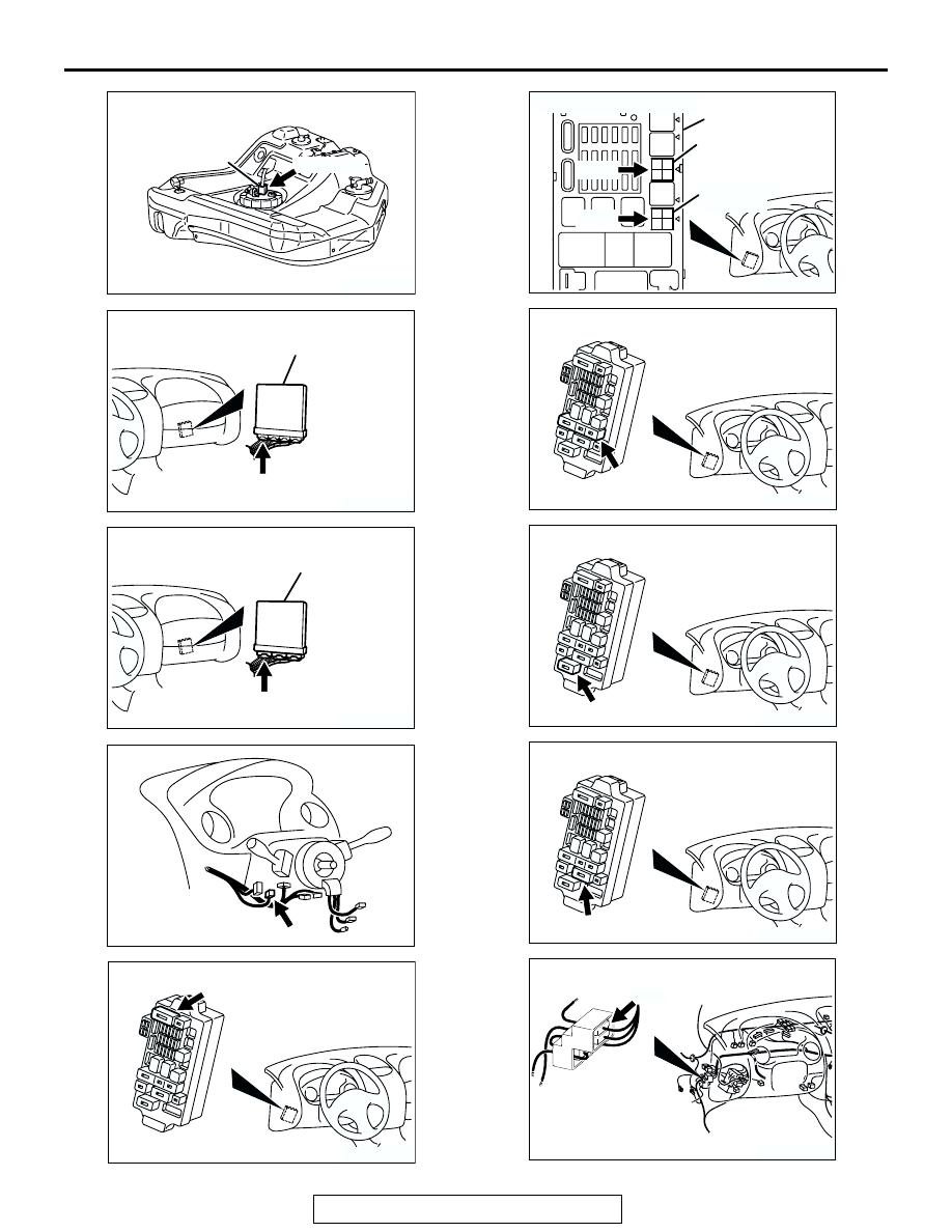
AK300096
D-17 (GR)
FUEL PUMP
MODULE
AB
CONNECTOR: D-17
AK300244
CONNECTOR: C-52 <A/T>
AC
PCM
C-52 (GR)
AK300091
CONNECTOR: C-51 <M/T>
ECM
AF
C-51 (GR)
AK300116
CONNECTOR: C-87
AB
C-87
AK300100
CONNECTOR: C-101
AB
C-101
3
4
1
2
3
4
1
2
3
4
1
2
3
4
1
2
3
4
1
2
3
4
1
2
3
4
1
2
AK300127
CONNECTORS: C-105, 107
FUEL PUMP
RELAY (2)
JUNCTION BLOCK
AB
FUEL PUMP
RELAY (1)
C-105
C-107
AK300123
CONNECTOR: C-108
AB
C-108
AK300124
CONNECTOR: C-111
AB
C-111
AK300125
CONNECTOR: C-112
AB
C-112
AK300118
CONNECTOR: C-89
AC
C-89