Mitsubishi Eclipse. Manual - part 457
MULTIPORT FUEL INJECTION (MFI) DIAGNOSIS
TSB Revision
MULTIPORT FUEL INJECTION (MFI) <3.0L>
13B-371
.
MONITOR EXECUTION CONDITIONS (Other
monitor and Sensor)
Other Monitor (There is no temporary DTC stored
in memory for the item monitored below)
• Misfire monitor
Sensor (The sensor below is determined to be
normal)
• Volume airflow sensor
• Engine coolant temperature sensor
• Intake air temperature sensor
• Barometric pressure sensor
• Throttle position sensor
.
DTC SET CONDITIONS
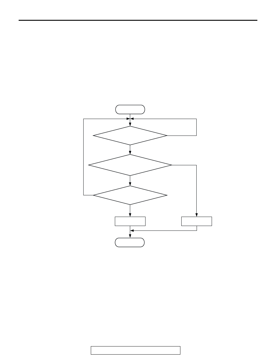
Logic Flow Chart
.
Check Conditions
• 20 seconds or more have passed since the start-
ing sequence was completed.
• Engine coolant temperature is higher than 76°C
(169
°F).
• Engine speed is higher than 1,200 r/min.
• Volumetric efficiency is at between 30 and 95
percent.
• Throttle position sensor output voltage is lower
then 4 volts.
• Except while fuel is being shut off.
• Monitoring time: 30 seconds.
Judgment Criteria
• Light bank heated oxygen sensor (front) output
voltage does not get across 0.5 volt within about
30 seconds.
.
OBD-ll DRIVE CYCLE PATTERN
Refer to , Diagnostic Function
− OBD-ll Drive Cycle −
Procedure 6
.
.
HEATED OXYGEN SENSOR (FRONT)
OUTPUT VOLTAGE CROSSES 0.5V?
START
END
NO
NO
NO
YES
Yes
YES
MALFUNCTION
GOOD
30secs HAVE PASSED?
MONITORING
CONDITIONS
AK203999