Mitsubishi Eclipse. Manual - part 456


  Index      Mitsubishi     Mitsubishi Eclipse - service repair manual 2004 year


Search            


Content   ..  454  455  456  457   ..


Mitsubishi Eclipse. Manual - part 456


MULTIPORT FUEL INJECTION (MFI) DIAGNOSIS

TSB Revision

MULTIPORT FUEL INJECTION (MFI) <3.0L>

13B-367

TROUBLESHOOTING HINTS (The most likely 
causes for this code to be set are: )

• Left bank heated oxygen sensor (front) deterio-

rated.

• ECM failed. <M/T>

• PCM failed. <A/T>

DIAGNOSIS

Required Special Tool:

• MB991958: Scan Tool (MUT-III Sub Assembly)

• MB991824: V.C.I.

• MB991827: USB Cable

• MB991911: Main Harness B

• MB998464: Test Harness

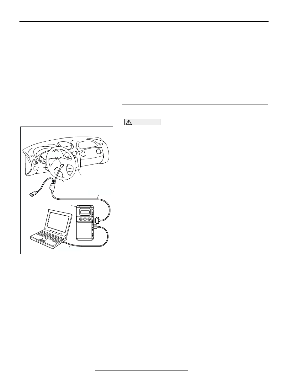
STEP 1. Using scan tool MB991958, check data list item 11: 
Heated Oxygen Sensor Bank 2, Sensor 1 (left front).

CAUTION

To prevent damage to scan tool MB991958, always turn the 
ignition switch to the "LOCK" (OFF) position before con-
necting or disconnecting scan tool MB991958.
(1) Connect scan tool MB991958 to the data link connector.
(2) Start the engine and run at idle.
(3) Set scan tool MB991958 to the data reading mode for item 

11, Heated Oxygen Sensor Bank 2, Sensor 1 (left front).

(4) Warm up the engine, 2,500r/min.

• Output voltage repeats 0.4 volt or less and 0.6 − 1.0 volt 

10 times or more within 10 seconds.

(5) Turn the ignition switch to the "LOCK" (OFF) position.
Q: Is the sensor operating properly?

YES : It can be assumed that this malfunction is intermittent. 

Refer to GROUP 00, How to Use Troubleshooting/ 
Inspection Service Points 

P.00-6

.

NO :  Replace the left bank heated oxygen sensor (front). 

Then go to Step 2.

AK300810

AB

MB991911

16-PIN

MB991827

MB991824 

MULTIPORT FUEL INJECTION (MFI) DIAGNOSIS

TSB Revision

MULTIPORT FUEL INJECTION (MFI) <3.0L>

13B-368

STEP 2. Check the left bank heated oxygen sensor (front).
(1) Disconnect the left bank heated oxygen sensor (front) 

connector B-24 and connect test harness special tool, 
MD998464, to the connector on the left bank heated oxygen 
sensor (front) side.

(2) Warm up the engine until engine coolant 80

°C (176°F) or 

higher.

CAUTION

Be very careful when connecting the jumper wires; incor-
rect connection can damage the right bank heated oxygen 
sensor (front).

(3) Use the jumper wires to connect terminal No. 1 (red clip) to 

the positive battery terminal and terminal No. 3 (blue clip) to 
the negative battery terminal.

(4) Connect a digital volt meter between terminal No. 2 (black 

clip) and terminal No. 4 (white clip).

(5) While repeatedly revving the engine, measure the left bank 

heated oxygen sensor (front) output voltage.

Standard value: 0.6 

 1.0 volt

Q: Is the voltage between 0.6 and 1.0 volt?

YES : Go to Step 3.
NO :  Replace the left bank heated oxygen sensor (front). 

Then go to Step 4.

AK300424

1

2

3

4

LEFT BANK 
HEATED OXYGEN
SENSOR (FRONT)

CONNECTOR: B-24

AB

B-24 (B)

HARNESS CONNECTOR:
COMPONENT SIDE

AKX01625AC

BLUE

RED

BLACK

JUMPER
WIRES

WHITE

MD998464

MULTIPORT FUEL INJECTION (MFI) DIAGNOSIS

TSB Revision

MULTIPORT FUEL INJECTION (MFI) <3.0L>

13B-369

STEP 3. Check harness connector B-24 at left bank heated 
oxygen sensor (front) and harness connector C-58, C-62 at 
ECM or C-55, C-59 at PCM for damage.
Q: Is the harness connector in good condition?

YES : Replace the PCM. Then go to Step 4.
NO :  Repair or replace it. Refer to GROUP 00E, Harness 

Connector Inspection 

P.00E-2

. Then go to Step 4.

AK300424

1

2

3

4

LEFT BANK 
HEATED OXYGEN
SENSOR (FRONT)

CONNECTOR: B-24

AB

B-24 (B)

HARNESS CONNECTOR:
COMPONENT SIDE

AK300441

65

43
50

42
49

41
48
60

61

64

46

47

58

59

67

68

45

56
66

52 51

44

53

62

54

63

57

55

80

87

81

94

85

82

84

93

86

98

99

74

92

73

83

88

91

95

97 96

100

89

78

71

90

76

77

75

72
79

CONNECTORS: C-58, C-62 <M/T>

C-58 (GR)

C-62 (GR)

AB

C-62 HARNESS CONNECTOR:
COMPONENT SIDE

C-58 HARNESS CONNECTOR:
COMPONENT SIDE

MULTIPORT FUEL INJECTION (MFI) DIAGNOSIS

TSB Revision

MULTIPORT FUEL INJECTION (MFI) <3.0L>

13B-370

STEP 4. Test the OBD-II drive cycle.
(1) Carry out a test drive with the drive cycle pattern. Refer to 

Diagnostic Function 

− OBD-II Drive Cycle − Procedure 4 − 

Heated Oxygen Sensor Monitor 

P.13B-7

.

(2) Check the diagnostic trouble code (DTC). 
Q: Is DTC P0153 set?

YES : Retry the troubleshooting.
NO :  The inspection is complete.

DTC P0154: Heated Oxygen Sensor No Activity Detected (bank 2, sensor 1)

.

HEATED OXYGEN SENSOR CIRCUIT NO 
ACTIVITY DETECTED (bank 2, sensor 1) CIRCUIT

• Refer to DTC P0152 − Heated Oxygen Sensor 

Circuit High Voltage (bank 2, sensor 1) 

P.13B-358

.

• Refer to DTC P0202, P0204, P0206 − Injector 

Circuit 

P.13B-521

.

.

CIRCUIT OPERATION

• Refer to DTC P0152 − Heated Oxygen Sensor 

Circuit High Voltage (bank 2, sensor 1) 

P.13B-358

.

• Refer to DTC P0202, P0204, P0206 − Injector 

Circuit 

P.13B-521

.

.

TECHNICAL DESCRIPTION

• The ECM <M/T> or PCM <A/T> effects air/fuel 

ratio feedback control in accordance with the sig-
nals from the left bank heated oxygen sensor 
(front).

• If the left bank heated oxygen sensor (front) has 

deteriorated, corrections will be made by the left 
bank heated oxygen sensor (rear).

• DTC P0154 is stored when abnormality of the 

air/fuel ratio feed back control system is detected.

.

DESCRIPTIONS OF MONITOR METHODS
Left bank heated oxygen sensor (front) output volt-

age does not cross 0.5 volt within specified 
period.

.

MONITOR EXECUTION
Continuous

AK300459

42

43

48

49

50

51

52

53

54

55

56

57

46 45 44

58

59

60

61

62

63

64

65

66

47

41

98

78

71

88

89

76

77

72
79
91

73
80

74

75

81
92

82

83

93

84

85

94

86

87

95

96

90

97

CONNECTORS: C-55, C-59 <A/T>

C-55 (GR)

C-59 (GR)

AB

C-59 HARNESS CONNECTOR:
COMPONENT SIDE

C-55 HARNESS CONNECTOR:
COMPONENT SIDE


Content   ..  454  455  456  457   ..