Mitsubishi Eclipse. Manual - part 340


  Index      Mitsubishi     Mitsubishi Eclipse - service repair manual 2004 year


Search            


Content   ..  338  339  340  341   ..


Mitsubishi Eclipse. Manual - part 340


MULTIPORT FUEL INJECTION (MFI) DIAGNOSIS

TSB Revision

MULTIPORT FUEL INJECTION (MFI) <2.4L>

13A-853

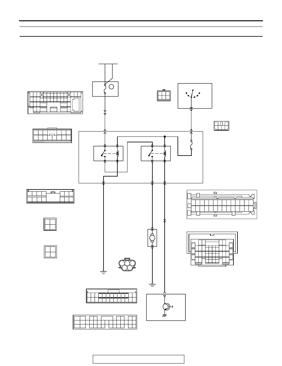
INSPECTION PROCEDURE 30: Fuel pump system.

AK103264

1 2 3

4

4 5 6

1 2

GREEN

GREEN-

BLA

CK

GREEN-

BLA

CK

WHITE

WHITE

3

BLA

CK

5

BLA

CK

BLA

CK

IG2

ST

LOCK

ACC

IG1

C-87

11

JUNCTION
BLOCK

R

IGNITION
SWITCH

RELAY BOX

ENGINE CONTROL
MODULE (ECM) <M/T>
OR
POWERTRAIN CONTROL
MODULE (PCM) <A/T>

FUEL
PUMP
RELAY (1)
C-107

FUEL
PUMP
RELAY (2)
C-105

FUEL PUMP
MODULE

12

2

      D-17
(MU802058)

1
C-101

14
C-108

11
C-108

M

GREEN

BLA

CK

5

4

C-50 <A/T>
(MU803784)

2

3 4

5 6

7 8

9

11 12 13 14 15 16 17 18 19 20

30

21 22 23

24 25

26 27 28 29

3132 33

34 35

1

10

Fuel Pump Circuit

OFF

1

3

2

6

4

2

OFF

ON

ON

4

3

1

2

BATTERY

C-28

7 8

5

3 4

35

34

10 11 12

2122 23 24

13 14 15

25 26 27

16

28

17

18 19 20

29

30 31

32 33

36 37

38

9

1 2

6

3 4

1 2

C-105

C-107

3 4

1 2

1

3

2

4 5 6

    C-111
MU801331

15 16

26 27 28 29

32 33 34

17 18 19 20 21 22 23 24 25

30 31

36 37

35

38

10

11 12 13

1 2 3

4 5 6 7 8 9

14

C-89

22 <M/T>
21 <A/T>

C-49 <M/T>
(MU803773)

7

6

5

9

8

10

20

23

4

17

3

16

2

15

1

14

11

24

12

25

13

26

18 19

21 22

1

6

4 5

11

10

1213

15

17

16

14

19

18

8 9

7

20

2 3

2122 23 2425 26 27 28

C-108

1

6

4 5

11

10

12 13 14

8 9

7

2 3

C-112

MU801857

1

6

4

5

11

10

12

1314

8 9

7

2 3

15

C-101

24

15A

MULTIPORT FUEL INJECTION (MFI) DIAGNOSIS

TSB Revision

MULTIPORT FUEL INJECTION (MFI) <2.4L>

13A-854

3

4

1

2

3

4

1

2

3

4

1

2

3

4

1

2

3

4

1

2

3

4

1

2

3

4

1

2

AK300127

CONNECTORS: C-105, 107

FUEL PUMP
RELAY (2)

JUNCTION BLOCK

AB

FUEL PUMP
RELAY (1)

C-105

C-107

AK300120AB

D-17 (GR)

CONNECTOR: D-17

FUEL TEMPERATURE 
SENSOR
(INTEGRATED IN 
 FUEL PUMP MODULE)

AK300060

ECM

CONNECTOR: C-49 <M/T>

AC

C-49 (G)

AK300060AD

C-50 (GR)

PCM

CONNECTOR: C-50 <A/T>

AK300116

CONNECTOR: C-87

AB

C-87

AK300119

CONNECTOR: C-28

AB

C-28

AK300062AB

CONNECTOR: C-101

C-101

AK300123

CONNECTOR: C-108

AB

C-108

AK300124

CONNECTOR: C-111

AB

C-111

AK300125

CONNECTOR: C-112

AB

C-112

MULTIPORT FUEL INJECTION (MFI) DIAGNOSIS

TSB Revision

MULTIPORT FUEL INJECTION (MFI) <2.4L>

13A-855

.

CIRCUIT OPERATION

• Battery positive voltage is applied to the fuel 

pump relay 1 (terminal No. 3) from the ignition 
switch-IG.
Ground is provided through terminal No. 2 to 
chassis ground.

• When the ignition switch is turned to the "ON" 

position, the battery positive voltage is applied to 
the fuel pump relay 2 (terminal No. 1) from the 
fuel pump relay 1 (terminal No. 1).

• A battery positive voltage is applied on the fuel 

pump relay 2 (terminal No. 3) from the ignition 
switch-IG.

• During cranking and while the engine is running, 

the ECM <M/T> or PCM <A/T> turns the power 
transistor in the ECM <M/T> or PCM <A/T> ON 
to ground the fuel pump relay 2 coil. With this, the 
fuel pump relay turns ON, and the battery positive 
voltage is supplied to the fuel pump from the fuel 
pump relay 2 (terminal No. 4).

.

TROUBLESHOOTING HINTS (The most likely 
causes for this code to be set are: ) 

• Malfunction of the fuel pump relay.

• Malfunction of the fuel pump.

• Improper connector contact, open or 

short-circuited harness wire.

• Malfunction of the ECM <M/T> or PCM <A/T>.

DIAGNOSIS

Required Special Tools:

• MB991958 (MUT-III Sub Assembly)

• MB991824: V.C.I.

• MB991827: USB Cable

• MB991911: Main Harness B

AK300118

CONNECTOR: C-89

AC

C-89

MULTIPORT FUEL INJECTION (MFI) DIAGNOSIS

TSB Revision

MULTIPORT FUEL INJECTION (MFI) <2.4L>

13A-856

STEP 1. Using scan tool MB991958, check actuator test 
item 07: Fuel Pump.

CAUTION

To prevent damage to scan tool MB991958, always turn the 
ignition switch to the "LOCK" (OFF) position before con-
necting or disconnecting scan tool MB991958.
(1) Connect scan tool MB991958 to the data link connector.
(2) Turn the ignition switch to the "ON" position.
(3) Set scan tool MB991958 to the actuator test mode for item 

07, Fuel Pump.

• An operation sound of the fuel pump should be heard.

(4) Turn the ignition switch to the "LOCK" (OFF) position.
Q: Is the fuel pump operating properly?

YES : That this malfunction is intermittent. Refer to GROUP 

00, How to Use Troubleshooting/Inspection Service 
Points 

P.00-6

NO :  Go to Step 2.

STEP 2. Check connector C-107 at fuel pump relay 1 and 
connector C-105 at fuel pump relay 2 for damage.
Q: Is the connector in good condition?

YES : Go to Step 3.
NO :  Repair or replace it. Refer to GROUP 00E, Harness 

Connector Inspection 

P.00E-2

. Then confirm that the 

malfunction symptom is eliminated.

AK300810

AB

MB991911

16-PIN

MB991827

MB991824 

3

4

1

2

3

4

1

2

3

4

1

2

3

4

1

2

3

4

1

2

3

4

1

2

3

4

1

2

AK300456

2 1

3

4

2 1

3

4

CONNECTORS: C-105, 107

C-105

C-107

AB

C-107 HARNESS CONNECTOR:
COMPONENT SIDE

C-105 HARNESS CONNECTOR:
COMPONENT SIDE


Content   ..  338  339  340  341   ..