Mitsubishi Colt Ralliart. Manual - part 759


  Index      Mitsubishi     Mitsubishi Colt Ralliart - service repair manual


Search            


Content   ..  757  758  759  760   ..


Mitsubishi Colt Ralliart. Manual - part 759


ON-VEHICLE SERVICE

MULTIPORT FUEL INJECTION (MPI) <4G1>

13B-361

FUEL TANK PUMP OPERATION CHECK

M1131002001510

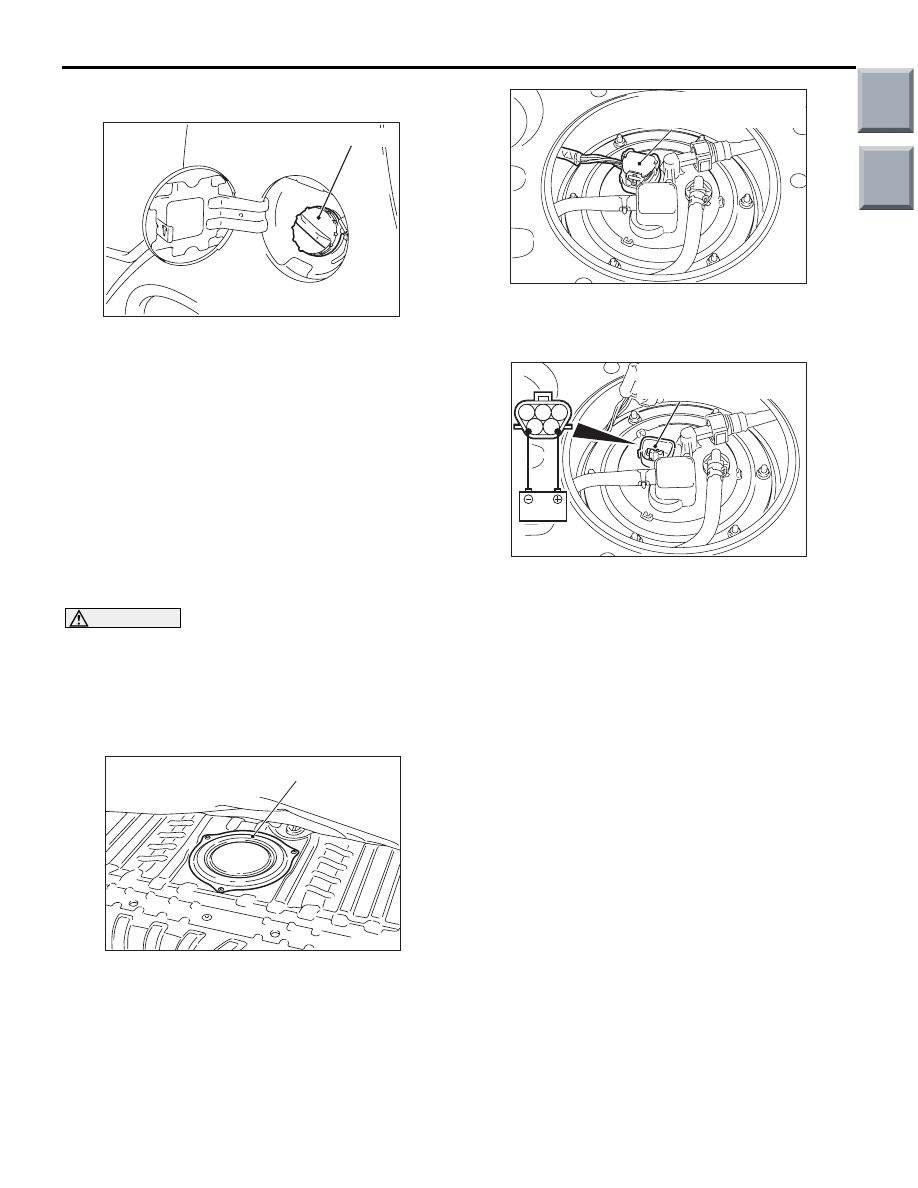
1. Remove the fuel tank cap.

NOTE: As the fuel tank pump is an in-tank type, 
the fuel tank pump sound is hard to hear. Then 
check the sound from the tank inlet.

2. Check the operating of the fuel tank pump by 

M.U.T.-III to force-drive the fuel tank pump.

3. Install the fuel tank cap.
4. If the fuel tank pump will not operate, check by 

using the following procedure. If normal, check 
the fuel tank pump drive circuit.
(1) Turn the ignition switch to the "LOCK" (OFF) 

position.

(2) Lift up the rear seat assembly.

CAUTION

Moulding type of floor carpet is used. Be careful 
not to change the shape of carpet when turning it 
over for operation.

(3) Remove the rear scuff plate, and turn over the 

floor carpet. (Refer to GROUP 52A, Interior 
Trims 

P.52A-11

).

(4) Remove the service hole cover.

(5) Disconnect the fuel tank pump and gauge 

assembly connector.

(6) Remove the fuel tank cap.

(7) When the fuel tank pump and gauge assembly 

connector terminal is connected directly to the 
battery, check if the sound of the fuel tank 
pump operation can be heard. If no operating 
sound is heard, replace the fuel tank pump 
(Refer to GROUP 13C, On-vehicle Service 

P.13C-3

).

NOTE: As the fuel tank pump is an in-tank 
type, the fuel tank pump sound is hard to hear. 
Then check the sound from the tank inlet.

(8) Install the fuel tank cap.
(9) Check for fuel pressure by pinching the fuel 

hose with fingertips.

(10)Connect the fuel tank pump and gauge 

assembly connector.

(11)Install the service hole cover.
(12)Return the floor carpet to the original state, 

and install the rear scuff plate. (Refer to 
GROUP 52A, Interior Trims 

P.52A-11

).

(13)Return the rear seat assembly to the original 

state.

AC207379AD

Fuel tank cap

AC207365AD

Service hole cover

AC403097AB

Fuel tank pump and
gauge assembly connector

1

4

2 3

5

AC403098 AB

Fuel tank pump and
gauge assembly connector

Main

Index

Group

TOC

ON-VEHICLE SERVICE

MULTIPORT FUEL INJECTION (MPI) <4G1>

13B-362

COMPONENT LOCATION

M1131002101799

Name

Symbol Name

Symbol

Accelerator pedal position sensor

Q

Fuel pump relay

N

Air flow sensor (with intake air temperature 
sensor)

H

Ignition coil (with power transistor)

B

A/C compressor relay

N

Injector

D

Camshaft position sensor

G

Oil feeder control valve

A

Cooling fan control relay

N

Oxygen sensor (front)

L

Oxygen sensor (rear)

R

Crank angle sensor

J

Purge control solenoid valve

E

Detonation sensor

K

Stop lamp switch

P

Diagnosis connector

O

Throttle position sensor

F

Engine control relay

N

Throttle valve control servo

F

Engine coolant temperature sensor

M

Throttle valve control servo relay

N

Engine-ECU (with barometric pressure 
sensor)

I

Waste gate solenoid valve

M

Fuel pressure control solenoid valve

C

AK600594

R

A

B

D

G

N

O

P

Q

C

E

F

H

I

L

M

J

K

AB

Main

Index

Group

TOC

ON-VEHICLE SERVICE

MULTIPORT FUEL INJECTION (MPI) <4G1>

13B-363

ENGINE CONTROL RELAY CONTINUITY 
CHECK

M1131050000914

FUEL PUMP RELAY CONTINUITY CHECK

M1131033000632

Tester 
Connection 
Terminal

Battery Voltage

Normal State

− 2

No voltage

Continuity

− 4

No voltage

No 
continuity

Voltage (Connect 
positive (+) terminal of 
battery to terminal No. 1 
and negative (

−) terminal 

of battery to terminal 
No. 2.)

Continuity

AK402727

3

1

2

4

AB

J/B (front side)

Engine control 
relay

Equipment side
connector

Tester 
Connection 
Terminal

Battery Voltage

Normal State

− 2

No voltage

Continuity

− 4

No voltage

No 
continuity

Voltage (Connect 
positive (+) terminal of 
battery to terminal No. 1 
and negative (

−) terminal 

of battery to terminal 
No. 2.)

Continuity

AK402728

3

1

2

4

AB

J/B (front side)

Fuel pump relay (2)

Fuel pump relay (1)

Equipment side
connector

Main

Index

Group

TOC

ON-VEHICLE SERVICE

MULTIPORT FUEL INJECTION (MPI) <4G1>

13B-364

THROTTLE VALVE CONTROL SERVO 
RELAY CONTINUITY CHECK

M1131053500134

INTAKE AIR TEMPERATURE SENSOR 
CHECK

M1131002800944

1. Disconnect the air flow sensor connector.
2. Measure resistance between terminals No. 1 and 

No. 4.

Standard value:

13 

 17 k (at 20°C)

5.4 

 6.6 k (at 0°C)

2.3 

 3.0 k (at 20°C)

1.0 

 1.5 k (at 40°C)

0.56 

 0.76 k (at 60°C)

0.31 

 0.43 k (at 80°C)

3. Remove the air flow sensor.

4. Measure resistance while heating the sensor 

using a hair drier.

Normal condition:

5. If the value deviates from the standard value or 

the resistance remains unchanged, replace the air 
flow sensor assembly.

6. Install the air flow sensor and tighten it to the 

specified torque.

Tightening torque: 1.8 

± 0.6 Nm

Tester 
Connection 
Terminal

Battery Voltage

Normal State

− 2

No voltage

Continuity

− 4

No voltage

No 
continuity

Voltage (Connect 
positive (+) terminal of 
battery to terminal No. 1 
and negative (

−) terminal 

of battery to terminal 
No. 2.)

Continuity

AK402729

3

1

2

4

AB

J/B (front side)

Throttle valve 
control servo relay

Equipment side
connector

Temperature (

°C)

Resistance (k

)

Higher

Smaller

AK402126

1

2

3 4

AC

Equipment side
connector

Intake air temperature 
sensor

AK203040

Intake air

temperature

sensor

AD

Main

Index

Group

TOC


Content   ..  757  758  759  760   ..