Mitsubishi Colt Ralliart. Manual - part 758
 

  Index      Mitsubishi     Mitsubishi Colt Ralliart - service repair manual


Search            


Content   ..  756  757  758  759   ..


Mitsubishi Colt Ralliart. Manual - part 758


TROUBLESHOOTING

MULTIPORT FUEL INJECTION (MPI) <4G1>

13B-357

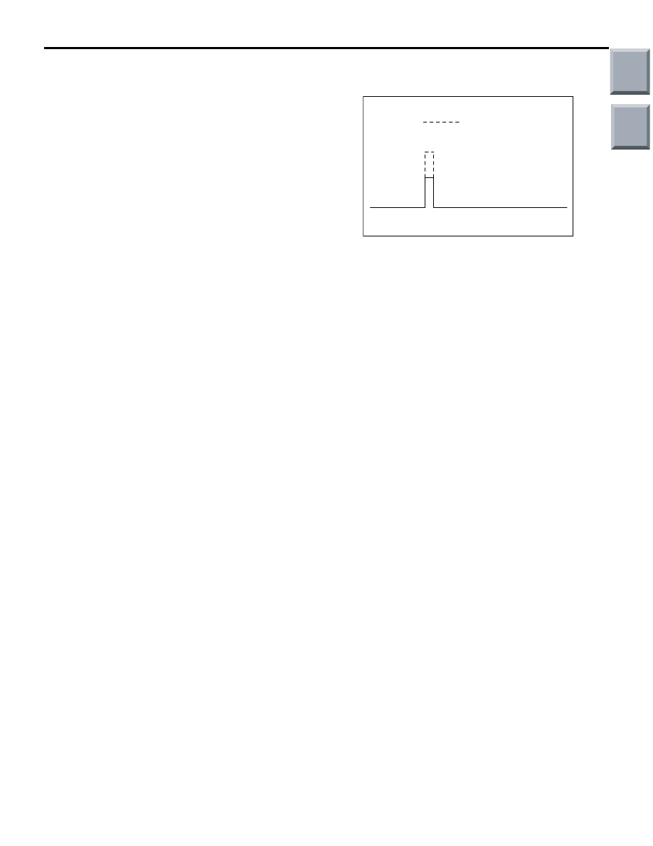
Description of Wave Pattern

• Condition of power transistor being in ON:

Condition in which the power transistor is turned ON 

and power is applied to the ignition coil primary 
side (dwell section). The time for the passage of 
power becomes long when the battery voltage is 
low, and becomes short when the battery voltage 
is high. Thus, control is exercised so that the pri-
mary current becomes constant when ignition 
occurs.

• Condition of power transistor being in OFF:

Condition in which the power transistor is turned OFF 

and no power transistor drive signal is output 
from the engine-ECU.

Wave Pattern Observation Points

• Check that the power transistor control signal 

(ignition timing) advances when the engine speed 
increases.

Example of Abnormal Wave Patterns

Wave pattern characteristics

Voltage is low.

Cause of problem

Open-circuit in ignition primary circuit

AK203246

Normal wave pattern

AD

Main

Index

Group

TOC

ON-VEHICLE SERVICE

MULTIPORT FUEL INJECTION (MPI) <4G1>

13B-358

ON-VEHICLE SERVICE

THROTTLE BODY (THROTTLE VALVE 
AREA) CLEANING

M1131001001142

1. Remove the air intake hose from the throttle body 

assembly.

2. Remove the throttle body assembly.

CAUTION

• Do not spray the cleaning fluid directly to the 

throttle valve.

• Make sure that the cleaning fluid does not 

enter the motor and the sensor through the 
shaft.

3. Spray cleaning fluid on a clean cloth.
4. Wipe off the dirt around the throttle valve with the 

cloth sprayed with cleaning fluid.

5. Install the throttle body assembly.
6. Attach the air intake hose.

FUEL PRESSURE TEST

M1131001901510

1. Release residual pressure from the fuel pipe line 

to prevent fuel gush out (Refer to 

P.13B-360

).

2. Disconnect the high-pressure fuel hose at the 

delivery pipe side.

CAUTION

Cover the hose connection with rags to prevent 
splash of fuel that could be caused by some 
residual pressure in the fuel pipe line.

3. Assemble the special tool Injector test set 

(MD998706) as shown in the figure.

a. Remove the mounting adapter for the injector 

and one side of another adapter.

b. Attach the special tool Quick connector 

(MB991990) and the special tool Hose adapter 
(MB992001) to the hose from which the adapters 
have been removed.

4. Attach the special tool between the delivery hose 

and the high-pressure fuel hose.

<When using the fuel pressure gauge>

a.

Via a suitable O-ring or gasket, install the fuel 
pressure gauge to the special tool for fuel pres-
sure measurement.

<When using the fuel pressure gauge set>

a.

Via a gasket, install the special tool Fuel pressure 
gauge set (MB991637 or MB991981) into the 
special tool for fuel pressure measurement.

AK402124AC

AK402073AC

MD998706

MB992001

MB991990

AK402074

O-ring or gasket

Delivery pipe

MD998706

Fuel pressure gauge

Fuel high-pressure 
hose

AC

AK402075AC

MB991637

MD998706

Fuel high-pressure 
hose

Gasket

Delivery pipe

AK402076

MD998706

MB991981

AC

Delivery pipe

Fuel high-pressure 
hose

Gasket

Main

Index

Group

TOC

ON-VEHICLE SERVICE

MULTIPORT FUEL INJECTION (MPI) <4G1>

13B-359

b. Connect lead wires of the fuel pressure gauge set 

to the power supply (cigarette lighter socket) and 
the special tool V.C.I. (MD991824).

5. Connect the M.U.T.-III to the diagnosis connector.

CAUTION

Always turn the ignition switch to the "LOCK" 
(OFF) position before connecting or disconnect-
ing the M.U.T.-III.
6. Turn the ignition switch to ON position (But do not 

start the engine).

7. Select "Item No. 07" from the M.U.T.-III actuator 

test to drive the fuel pump. Check that there are 
no fuel leaks from any parts under fuel pressure.

8. Finish the actuator test or turn the ignition switch 

to "LOCK" (OFF) position.

9. Start the engine and run at idle.
10.Measure fuel pressure while the engine is running 

at idle.

Standard value: Approximately 230 kPa

11.Remove the vacuum hose from the fuel pressure 

regulator, and measure fuel pressure while 
clogging the hose end with your finger.

Standard value: Approximately 289 

 299 

kPa

12.Check to see that fuel pressure at idle does not 

drop even after the engine has been accelerated 
several times.

13.While repeating engine acceleration, lightly push 

the fuel return hose with your finger to check that 
there is fuel pressure also in the return hose.
NOTE: Fuel pressure in the return hose will be 
lost if a flow rate of fuel is insufficient.

14.If any of fuel pressure measurement in steps 9 to 

12 is outside the standard value, troubleshoot and 
repair according to the table below.

AK402122

AC

Vacuum 
hose

Symptom

Probable cause

Remedy

• Fuel pressure too low

• Fuel pressure drops after 

acceleration

• No fuel pressure in fuel return 

hose

Clogged fuel filter

Replace fuel filter

Fuel leaking to return side due to 
poor fuel regulator valve seating or 
settled spring

Replace fuel pressure regulator

Low fuel pump delivery pressure

Replace fuel pump

Fuel pressure too high

Binding valve in fuel pressure 
regulator

Replace fuel pressure regulator

Clogged fuel return hose or pipe

Clean or replace hose and pipe

Fuel pressure remains unchanged 
whether vacuum hose is 
connected or disconnected

Damaged vacuum hose or clogged 
nipple

Replace vacuum hose or clean 
nipple

Main

Index

Group

TOC

ON-VEHICLE SERVICE

MULTIPORT FUEL INJECTION (MPI) <4G1>

13B-360

15.Stop the engine and check change of fuel 

pressure gauge reading. Normal if the reading 
does not drop within 2 minutes. If it does, observe 
the rate of drop and troubleshoot and repair 
according to the table below.

16.Release residual pressure from the fuel pipe line.
17.Remove the special tool from the delivery pipe.

CAUTION

Cover the hose connection with rags to prevent 
splash of fuel that could be caused by some 
residual pressure in the fuel pipe line.
18.Fit the high-pressure fuel hose to the delivery 

hose.

19.Check for any fuel leaks by following the 

procedure in step 7.

20.Disconnect the M.U.T.-III.

FUEL PUMP CONNECTOR 
DISCONNECTION (HOW TO REDUCE 
PRESSURIZED LINES)

M1131000901357

WARNING

When removing the fuel pipe, etc., release 
fuel pressure to prevent fuel spray.

1. Lift up the rear seat assembly.

CAUTION

Moulding type of floor carpet is used. Be careful 
not to change the shape of carpet when turning it 
over for operation.
2. Remove the rear scuff plate, and turn over the 

floor carpet. (Refer to GROUP 52A, Interior Trims 

P.52A-11

).

3. Remove the service hole cover.

4. Disconnect the fuel tank pump and gauge 

assembly connector.

5. Crank the engine for at least two seconds.
6. If the engine is not started, turn the ignition switch 

to the "LOCK" (OFF) position.

7. If the engine is started, turn the ignition switch to 

the "LOCK" (OFF) position after the engine 
stopped.

8. Connect the fuel tank pump and gauge assembly 

connector.

9. Install the service hole cover.
10.Return the floor carpet to the original state, and 

install the rear scuff plate. (Refer to GROUP 52A, 
Interior Trims 

P.52A-11

).

11.Return the rear seat assembly to the original 

state.

Symptom

Probable cause

Remedy

Fuel pressure drops gradually 
after engine is stopped

Leaky injector

Replace injector

Leaky fuel pressure regulator valve 
seat

Replace fuel pressure regulator

Fuel pressure drops sharply 
immediately after engine is 
stopped

Check valve in fuel pump is held 
open

Replace fuel pump

AC207365AD

Service hole cover

AC403097AB

Fuel tank pump and
gauge assembly connector

Main

Index

Group

TOC


Content   ..  756  757  758  759   ..