Mitsubishi Colt Ralliart. Manual - part 757
TROUBLESHOOTING
MULTIPORT FUEL INJECTION (MPI) <4G1>
13B-353
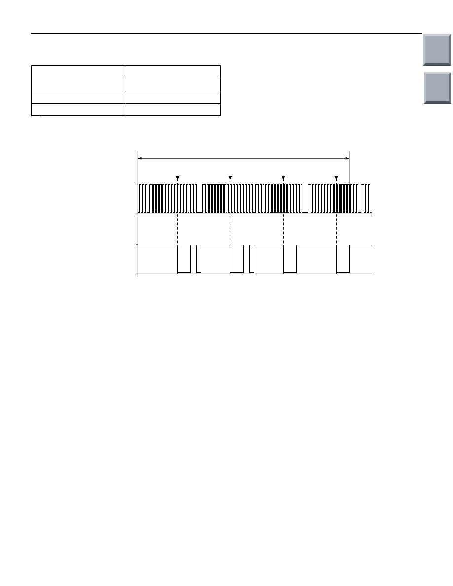
Standard Wave Pattern
Observation condition
Description of Wave Pattern
• The camshaft position sensor detects the com-
pression top dead center of each cylinder.
Observing this signal as well as other control sig-
nals simultaneously allows cylinder identification
to be achieved.
• The crank angle sensor detects the crank angle
of each cylinder. 72 crank angle sensor high sig-
nals (including missing tooth) are output at equal
spaces per two revolutions of the engine.
Wave Pattern Observation Points
• Check that the wave pattern becomes shorter
when the engine speed increases.
Function
Special patterns
Pattern height
Low
Pattern selector
Display
Engine
Idle
AK204111AC
(V)
5
0
5
0
No. 1TDC
No. 3TDC
No. 4TDC
No. 2TDC
time
Standard wave pattern
Crank angle
sensor output
wave pattern
Camshaft position
sensor output
wave pattern
2 engine revolutions
(1 camshaft revolution)
TDC: Top dead centre
Main
Index
Group
TOC