Mitsubishi Colt Ralliart. Manual - part 666
TROUBLESHOOTING
AUTOMATIC AIR CONDITIONER
55B-25
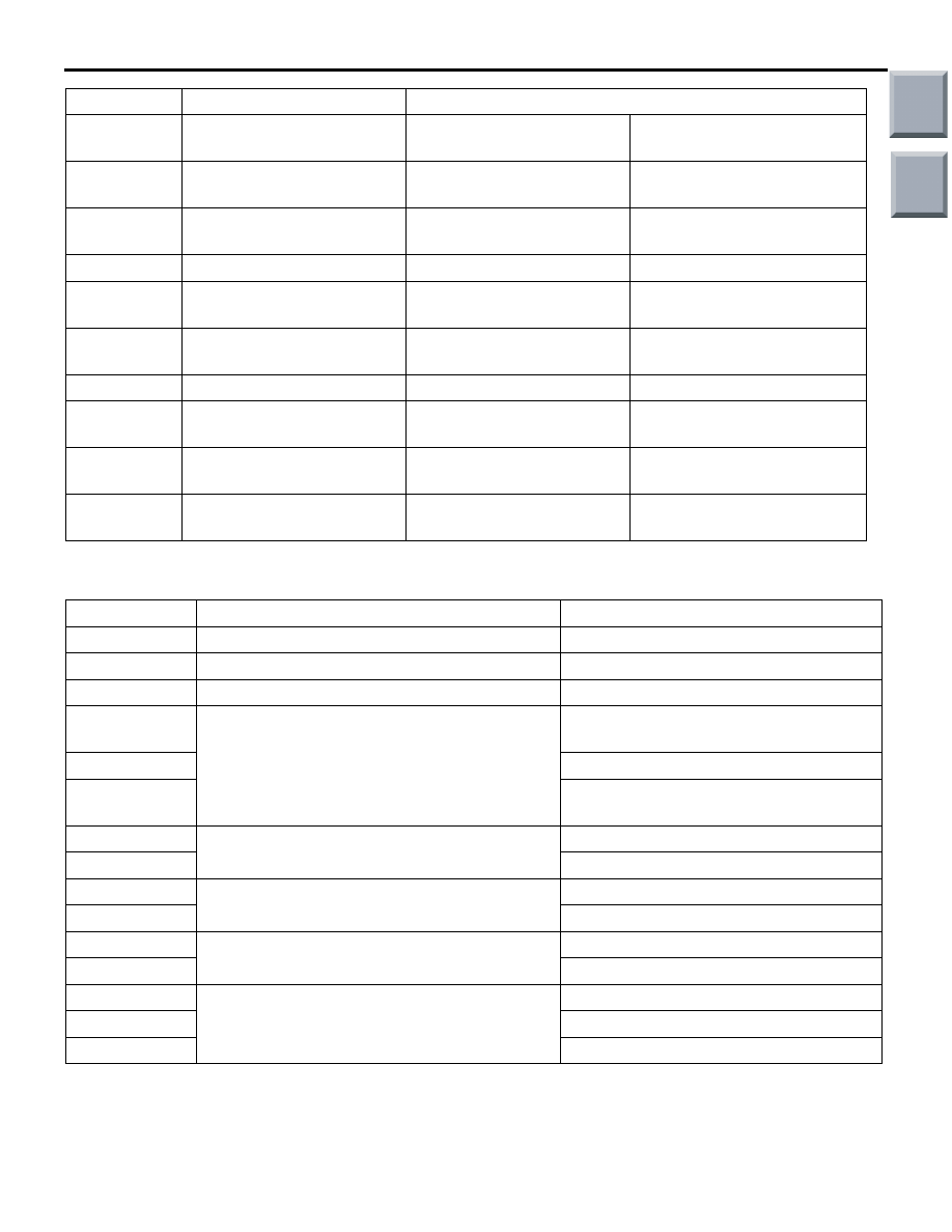
ACTUATOR TEST TABLE
M1554005200263
Item No.
Check items
Drive content
01
Blower motor: OFF
Stop
02
Blower motor: 8 speed
Middle speed
03
Blower motor: 16 speed
High speed
10
Air mixing damper control motor
Opening angle: Approximately 0% (MAX
COOL)
11
Opening angle: Approximately 50%
12
Open angle: Approximately 100% (MAX
COOL)
30
Outside/Inside air selection damper control
motor
Moved to recirculation-side
31
Moved to outside air-side
40
Rear defogger switch
OFF
41
ON
09*
Condenser fan
Stop
0B*
OPERATION
50*
Idle-up requirement
OFF
51*
Low-load
52*
High-load
NOTE: *: Drive at the engine operation
37
Outside/Inside air selection
switch
Ignition switch: ON
Display the outside/inside air
selection switch status
40
Abnormal low pressure
judgement
Ignition switch: ON
Displays the abnormal low
pressure judgement
41
Refrigerant leaks judgement Ignition switch: ON
Display the refrigerant leaks
judgement
42
DEF position flag
Ignition switch: ON
Display the DEF position flag
43
Forcible DEF position flag
Ignition switch: ON
Display the forcible DEF
position flag
44
Forcible DEF DRY flag
Ignition switch: ON
Display the forcible DEF DRY
flag
45
MAX COOL DRY flag
Ignition switch: ON
MAX COOL DRY flag status
46
MAX COOL recirculation
flag
Ignition switch: ON
Display the MAX COOL inside
air flag
47
MAX HOT A/C OFF flag
Ignition switch: ON
Display the MAX HOT A/C
OFF flag
48
MAX HOT fresh flag
Ignition switch: ON
Display the AX HOT outside
air flag
Item No.
Check items
Check contents
Main
Index
Group
TOC