Mitsubishi Colt Ralliart. Manual - part 664


  Index      Mitsubishi     Mitsubishi Colt Ralliart - service repair manual


Search            


Content   ..  662  663  664  665   ..


Mitsubishi Colt Ralliart. Manual - part 664


TROUBLESHOOTING

AUTOMATIC AIR CONDITIONER

55B-17

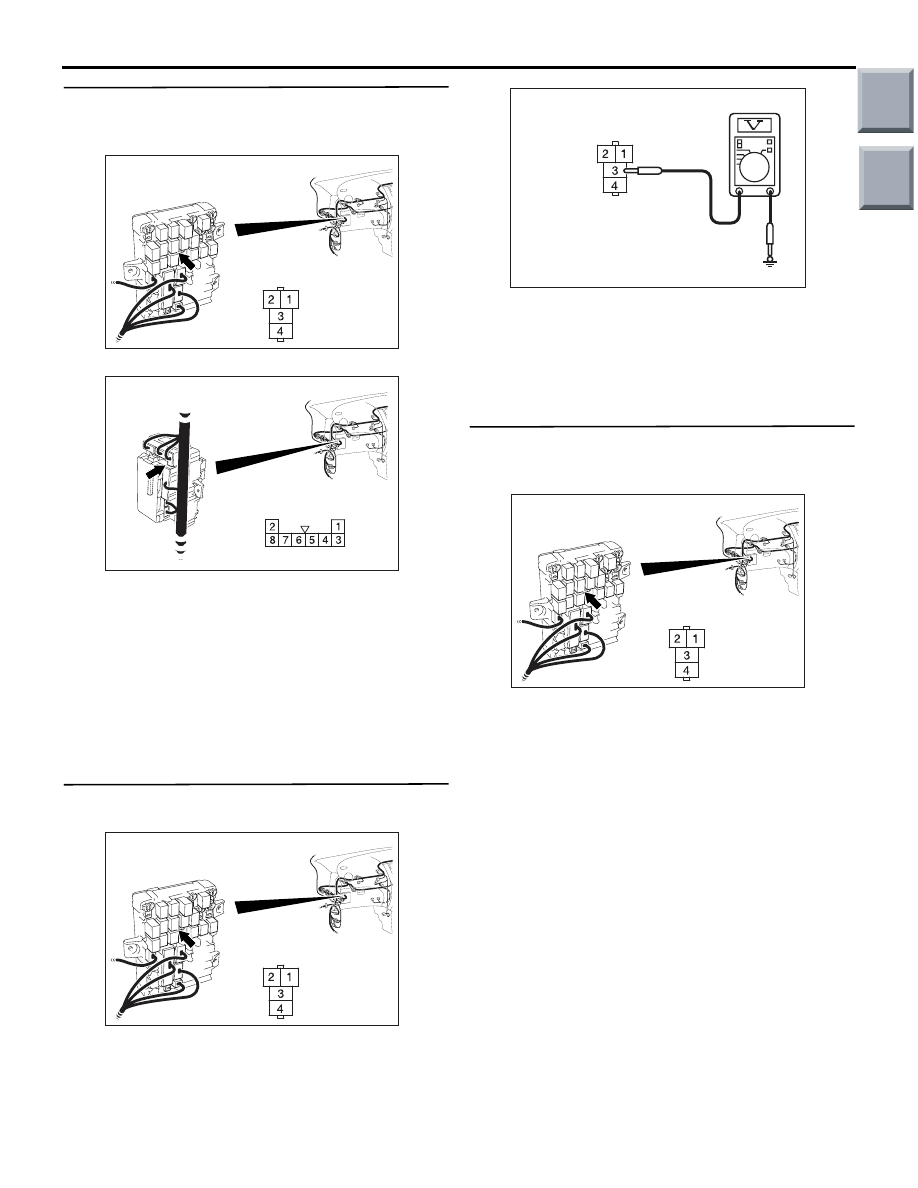
Step 8. Check the wiring harness between B-116 
blower relay connector terminal No.1 and the 
ignition switch (IG2).

AC313824

Connector: B-116

AD

Junction block side

Junction block (Front view)

NOTE: 

AC313826

Harness side

AE

Connector: B-130

Junction block (Rear view)

Prior to the wiring harness inspection, check junction 
block connector B-130, and repair if necessary.

• Check the blower relay power supply line for 

open circuit.

Q: Is the check result normal?

YES : 

The trouble can be an intermittent 

malfunction (Refer to GROUP 00, How to 
Cope with Intermittent Malfunction 

P.00-13

).

NO : 

Repair the wiring harness.

Step 9. Voltage measurement at B-116 blower 
relay connector.

AC313824

Connector: B-116

AD

Junction block side

Junction block (Front view)

(1) Remove the relay, and measure at the junction 

block side.

AC310507 FJ

Connector C-116 
(Junction block side)

(2) Voltage between terminal 3 and body earth.

OK: System voltage

Q: Is the check result normal?

YES : 

Go to Step 11.

NO : 

Go to Step 10.

Step 10. Check the wiring harness between B-116 
blower relay connector terminal No.3 and fusible 
link (6).

AC313824

Connector: B-116

AD

Junction block side

Junction block (Front view)

NOTE: Prior to the wiring harness inspection, check 
junction block connector B-116, and repair if neces-
sary.

• Check the blower relay power supply line for 

open circuit.

Q: Is the check result normal?

YES : 

The trouble can be an intermittent 

malfunction (Refer to GROUP 00, How to 
Cope with Intermittent Malfunction 

P.00-13

).

NO : 

Repair the wiring harness.

Main

Index

Group

TOC

TROUBLESHOOTING

AUTOMATIC AIR CONDITIONER

55B-18

Step 11. Check the wiring harness between B-116 
blower relay connector terminal No.4 and B-10 
blower motor connector terminal No.1.

AC313822

Connector: B-10

AK

Harness side

AC313824

Connector: B-116

AD

Junction block side

Junction block (Front view)

NOTE: 

AC313826

Harness side

AE

Connector: B-130

Junction block (Rear view)

Prior to the wiring harness inspection, check junction 
block connector B-130, and repair if necessary.

• Check the blower relay earth wires for open cir-

cuit.

Q: Is the check result normal?

YES : 

Go to Step 12.

NO : 

Repair the wiring harness.

Step 12. Check the wiring harness between B-116 
blower relay connector terminal No.2 and B-15 
combination meter connector terminal No.12.

AC313822 AB

Connector: B-15

Harness side

B-15 (B)

AC313824

Connector: B-116

AD

Junction block side

Junction block (Front view)

NOTE: 

AC313826 AF

Connector: B-131

Junction Block (Rear view)

Harness side

Prior to the wiring harness inspection, check junction 
block connector B-131, and repair if necessary.

• Check the blower relay power supply line for 

open circuit.

Q: Is the check result normal?

YES : 

The trouble can be an intermittent 

malfunction (Refer to GROUP 00, How to 
Cope with Intermittent Malfunction 

P.00-13

).

NO : 

Repair the wiring harness.

Step 13. Check the blower motor
Refer to GROUP 55A 

P.55A-61

.

Q: Is the check result normal?

YES : 

Go to Step 14.

NO : 

Replace the outside/inside air selection 
damper control motor.

Main

Index

Group

TOC

TROUBLESHOOTING

AUTOMATIC AIR CONDITIONER

55B-19

Step 14. Connector check: B-05 power transistor 
controller connector

AC313820AL

Connector: B-05

Harness side

B-05 (B)

Q: Is the check result normal?

YES : 

Go to Step 15.

NO : 

Repair the connector.

Step 15. Resistance measurement at the B-05 
power transistor connector.

AC313820AL

Connector: B-05

Harness side

B-05 (B)

(1) Disconnect the connector, and measure at the 

wiring harness side.

AC310506 EJ

Connector B-05 
(Harness side)

(2) Continuity between terminal 5 and body earth

OK: Continuity (Less than 2 

)

Q: Is the check result normal?

YES : 

Go to Step 17.

NO : 

Go to Step 16.

Step 16. Check the wiring harness between B-05 
power transistor connector terminal No.5 and 
body earth.

AC313820AL

Connector: B-05

Harness side

B-05 (B)

• Check the blower linear controller earth line for 

open circuit.

Q: Is the check result normal?

YES : 

The trouble can be an intermittent 

malfunction (Refer to GROUP 00, How to 
Cope with Intermittent Malfunction 

P.00-13

).

NO : 

Repair the wiring harness.

Step 17. Check the wiring harness between B-10 
blower motor connector terminal No.2 and B-05 
power transistor controller connector terminal 
No.4.

AC313820AL

Connector: B-05

Harness side

B-05 (B)

AC313822

Connector: B-10

AK

Harness side

• Check the blower linear controller power supply 

line for open circuit.

Q: Is the check result normal?

YES : 

Go to Step 18.

NO : 

Repair the wiring harness.

Main

Index

Group

TOC

TROUBLESHOOTING

AUTOMATIC AIR CONDITIONER

55B-20

Step 18. Check the wiring harness between B-15 
combination meter connector (terminals 19 and 
20) and B-05 power transistor controller 
connector (terminals 1 and 3).

AC313820AL

Connector: B-05

Harness side

B-05 (B)

AC313822 AB

Connector: B-15

Harness side

B-15 (B)

• Check the blower linear controller power supply 

line for open circuit.

Q: Is the check result normal?

YES : 

Go to Step 19.

NO : 

Repair the wiring harness.

Step 19. Replace the power transistor and 
recheck the trouble symptom
 Check that the blower motor operates normally.

Q: Is the check result normal?

YES : 

This diagnosis is complete.

NO : 

Replace the combination meter (meter and 
A/C-ECU).

Main

Index

Group

TOC


Content   ..  662  663  664  665   ..