Mitsubishi Colt Ralliart. Manual - part 539


  Index      Mitsubishi     Mitsubishi Colt Ralliart - service repair manual


Search            


Content   ..  537  538  539  540   ..


Mitsubishi Colt Ralliart. Manual - part 539


COMPRESSOR ASSEMBLY

HEATER, AIR CONDITIONER AND VENTILATION

55A-64

REMOVAL SERVICE POINTS
<<A>> FLEXIBLE SUCTION HOSE AND 
FLEXIBLE DISCHARGE HOSE DISCON-
NECTION

CAUTION

Use the plug which is not breathable because 
A/C compressor oil or receiver have high hygro-
scopicity.
Plug the removed nipple of the pipe, hose and 
expansion valve to prevent the entry of dust and dirt.

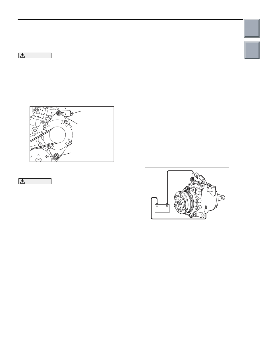
<<B>> A/C COMPRESSOR DRIVE BELT 
REMOVAL

AC310987AB

Nut for alternator
pivot bolt

Adjusting bolt

Alternator fixing nut

1. Loosen the nut for alternator pivot bolt and 

alternator fixing nut.

CAUTION

To reuse the drive belt, draw an arrow indicating 
the rotating direction (clockwise) on the back of 
the belt using chalk, etc.
2. Turn the adjusting bolt in the anti-clockwise 

direction (to the left) to remove the drive belt.

<<C>> A/C COMPRESSOR REMOVAL

Be careful not to spill the A/C compressor oil and 
remove the A/C compressor.

INSTALLATION SERVICE POINT
>>A<< A/C COMPRESSOR INSTALLA-
TION

When installing the new A/C compressor, install the 
A/C compressor after adjusting the oil volume as fol-
lows.
1. Measure the oil of A/C compressor removed.(X 

cm

3

 )

2. Drain the oil (Y cm

3

) given by the following 

expression from a new A/C compressor, and then 
install the A/C compressor.

140 cm

3

 - X cm

3

  = Y cm

3


NOTE: 

.

140 cm

3

 shows the oil volume contained in the 

new A/C compressor.

Y cm

3

 shows the oil volume stored in the 

refrigerant line, condenser, and cooling unit, 
etc.

INSPECTION

M1552004500243

COMPRESSOR MAGNETIC CLUTCH 
OPERATION CHECK

AC208432

Connect the connector battery to positive battery ter-
minal in the A/C compressor, and then earth the bat-
tery (

−) terminal to the A/C compressor itself. At this 

time, check that the magnetic clutch operating sound 
can be heard.

Main

Index

Group

TOC

COMPRESSOR ASSEMBLY

HEATER, AIR CONDITIONER AND VENTILATION

55A-65

DISASSEMBLY AND ASSEMBLY

M1552004600682

AC206957

3

N

4

5

6

7

8

10

9

AC

16 ± 1 N·m

1

2

Cooling temperature switch 
disassembly steps 

1.

Snap ring

2.

Cooling temperature switch
Magnetic clutch disassembly 

>>

D

<<

Air gap adjustment

<<

A

>>

>>

C

<<

3.

Self-locking nut

4.

Armature

>>

B

<<

5.

Snap ring

6.

Rotor

>>

B

<<

7.

Snap ring

>>

A

<<

8.

A/C compressor coil

9.

Shim

10. A/C compressor

DISASSEMBLY SERVICE POINT
<<A>> SELF-LOCKING NUT REMOVAL

AC208431AB

MB991386

MB991367

Use the special tools to remove the self-locking nut.

• Special spanner (MB991367)

• Pin (MB991386)

Magnetic clutch disassembly 

Main

Index

Group

TOC

COMPRESSOR ASSEMBLY

HEATER, AIR CONDITIONER AND VENTILATION

55A-66

ASSEMBLY SERVICE POINTS
>>A<< A/C COMPRESSOR COIL INSTAL-
LATION

AC208397

Compressor unit
pin hole

AB

Field core 
projection

Install the A/C compressor coil while aligning the pin 
hole of A/C compressor itself with the protrusion of 
A/C compressor coil

>>B<< SNAP RING INSTALLATION

AC209126AB

Snap ring

Rotor

Clutch coil

Tapered part

Use the snap ring plier and Install the snap ring so 
that the taper faces the outside.

>>C<< SELF-LOCKING NUT 
INSTALLATION

Use the special tool as during removal to secure the 
armature and tighten the self-locking nut.

>>D<< AIR GAP ADJUSTMENT

AC208396

Thickness 
gauge

AB

Check that the air gap of clutch satisfies the standard 
value. If not within the standard value, use shims to 
adjust it.

Standard value: 0.25 

 0.5 mm

INSPECTION

M1552004700128

COOLING TEMPRATURE SWITCH

CAUTION

Do not heat than necessary.

AC102063 AB

Thermometer

Engine oil

1. Immerse the refrigerant temperature sensor probe 

into engine oil to heat the sensor probe.

AC103406

100˚C

130˚C

AE

Continuity

No 
continuity

Oil temperature

2. If the oil temperature reaches the standard value, 

there should be continuity between the switch 
terminals.

Switch status

Operating 
temperature 

°C

Being turned off (No continuity) 130
Being turned on (2

Ω or less)

100

NOTE: When the oil temperature is 130

°

C or 

more and there is no continuity, the resistance will 
not be 2

 or lower until the oil temperature 

reduces to 100 

°

C or less.

Main

Index

Group

TOC

CONDENSER ASSEMBLY

HEATER, AIR CONDITIONER AND VENTILATION

55A-67

CONDENSER ASSEMBLY

REMOVAL AND INSTALLATION

M1552015400176

Pre-removal and Post-installation Operation
Refrigerant draining and Refilling (Refer to 

P.55A-48

and 

P.55A-48

.)

AC206955

1, 2

8

8

N

8

N

2

1

4.9 ± 1.0 N·m

12 ± 2 N·m

5

8

N

6

7

4

AB

3

-Pipe coupling

A/C compressor oil: 
SUN PAG 56

Removal steps 

<<

A

>>

1.

Flexible discharge hose connection

<<

A

>>

2.

Liquid pipe A connection

3.

Front end upper bar

4.

Condenser assembly

5.

Condenser pipe

6.

Receiver

7.

Condenser

8.

O-ring

REMOVAL SERVICE POINT
<<A>> FLEXIBLE DISCHARGE HOSE 
AND LIQUID PIPE A DISCONNECTION

CAUTION

Use the plug which is not breathable because 
A/C compressor oil or receiver have high hygro-
scopicity.
Plug the removed nipple of the pipe, hose and 
expansion valve to prevent the entry of dust and dirt.

Main

Index

Group

TOC


Content   ..  537  538  539  540   ..