Mitsubishi Colt Ralliart. Manual - part 538
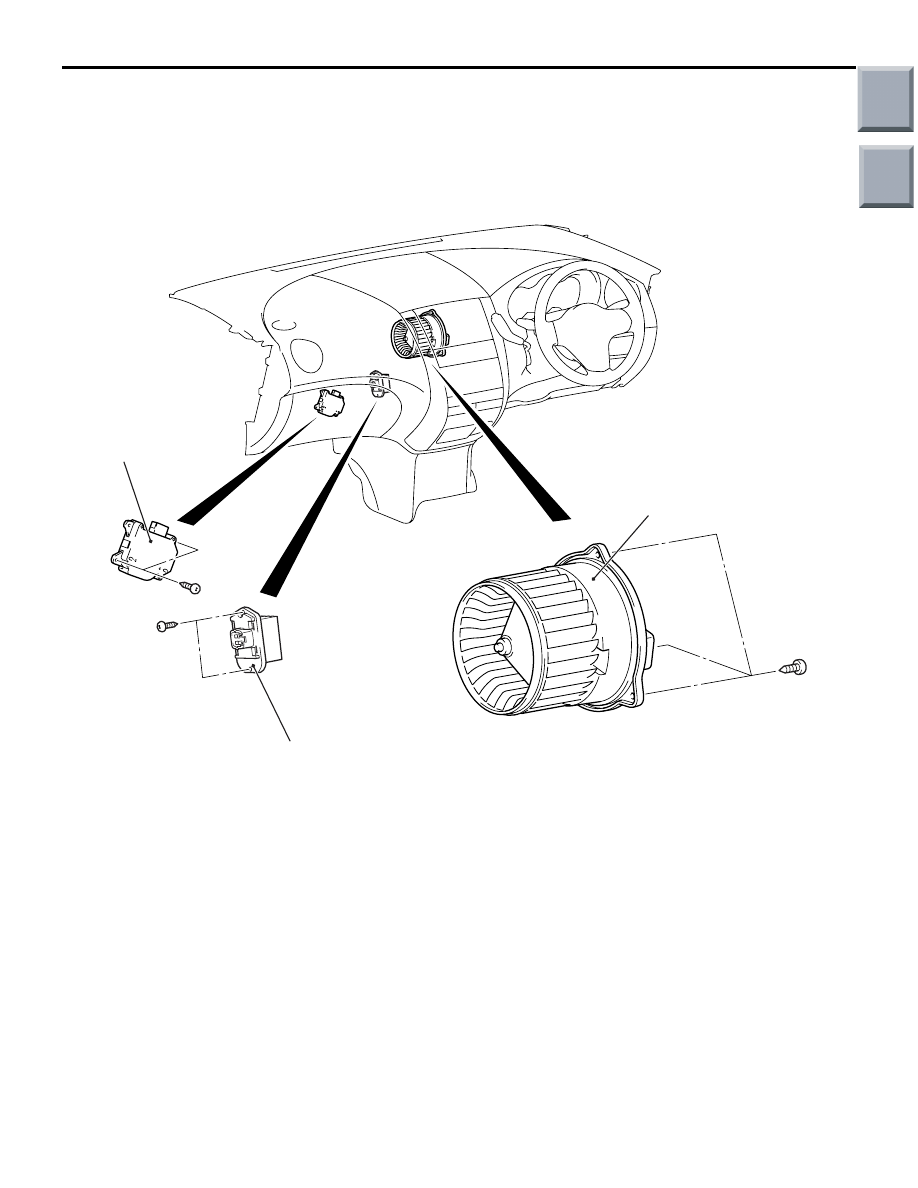
RESISTOR, BLOWER MOTOR AND OUTSIDE/INSIDE AIR SELECTION DAMPER CONTROL MOTOR
HEATER, AIR CONDITIONER AND VENTILATION
55A-60
RESISTOR, BLOWER MOTOR AND OUTSIDE/INSIDE AIR
SELECTION DAMPER CONTROL MOTOR
REMOVAL AND INSTALLATION
M1552015200105
AC207764AC
3
2
1
Resistor removal step
•
Glove box (Refer to GROUP 52A,
Instrument Panel
•
Front scuff plate and cowl side trim
(Refer to GROUP 52A, Interior Trim
<<
A
>>
1.
Resistor
Blower motor removal step
•
Parking brake pedal assembly
(GROUP 36, Parking Brake Pedal
.)
•
Transmission control cable dash
panel side installation (Refer to
GROUP 23, Transmission control
•
Diagnosis connector bracket
•
Foot heater duct LH (Refer to
2.
Blower motor
Outside/Inside air selection
damper control motor removal
step
•
Glove box (Refer to GROUP 52A,
Instrument Panel
3.
Outside/Inside air selection damper
control motor
Blower motor removal step
Main
Index
Group
TOC