Mitsubishi Colt Ralliart. Manual - part 516
INSTRUMENT PANEL ASSEMBLY
INTERIOR
52A-4
CAUTION
• Refer to GROUP 52B, SRS Service Precautions
and Driver’s, Front Passenger’s Air bag
Module(s) and Clock Spring
before removing the passenger side air bag module.
•
Pre-removal and Post-installation Operation
• Removal and Installation of Front Pillar Trim (Refer to
• Removal and Installation of Hood Lock Release Handle
(Refer to GROUP 42, Hood
).
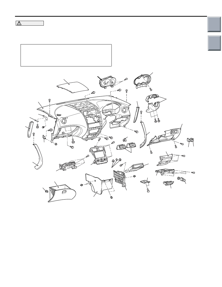
AC400406
2
3
1
23
8
4
5 6
10
19
13
12
11
9
20
16
14
20
15
22
21
18
8
23
24
7
AB
17
e
j
l
l
e
l
l
l
l
e
g
j
c c
e
e
a
e
f
f
f
e
e
m
27
26
25
l
e
k
Do not subject the SRS-ECU to any shocks when removing or installing the instrument panel.
Removal steps
1.
Steering column cover
<<
A
>>
2.
Combination meter bezel
3.
Combination meter assembly
4.
Lower panel
5.
Fog lamp switch <Vehicles with fog
lamp>
6.
Remote control mirror switch
•
Steering wheel (refer to GROUP
37, Steering Wheel
•
Air bag module (refer to GROUP
52B, Driver’s, Front Passenger’s
Air Bag Module(s) and Clock Spring
•
Steering shaft (refer to GROUP 37,
Steering Shaft
7.
Upper centre panel
8.
Console panel
9.
Ashtray
10. Lower centre panel
11. Cigarette lighter
12. Ashtray cover
13. Parcel box bracket
14. Air control knob
15. Heater control panel
16. Hazard lamp switch
17. Air outlet
18. Radio assembly
Removal steps (Continued)
Main
Index
Group
TOC