Mitsubishi Colt Ralliart. Manual - part 486


  Index      Mitsubishi     Mitsubishi Colt Ralliart - service repair manual


Search            


Content   ..  484  485  486  487   ..


Mitsubishi Colt Ralliart. Manual - part 486


COLUMN SWITCH

CHASSIS ELECTRICAL

54A-89

COLUMN SWITCH

SPECIAL TOOL

M1543000602343

Tool

Number

Name

Application

MB990784

MB990784

Ornament 
remover

Removal of column cover

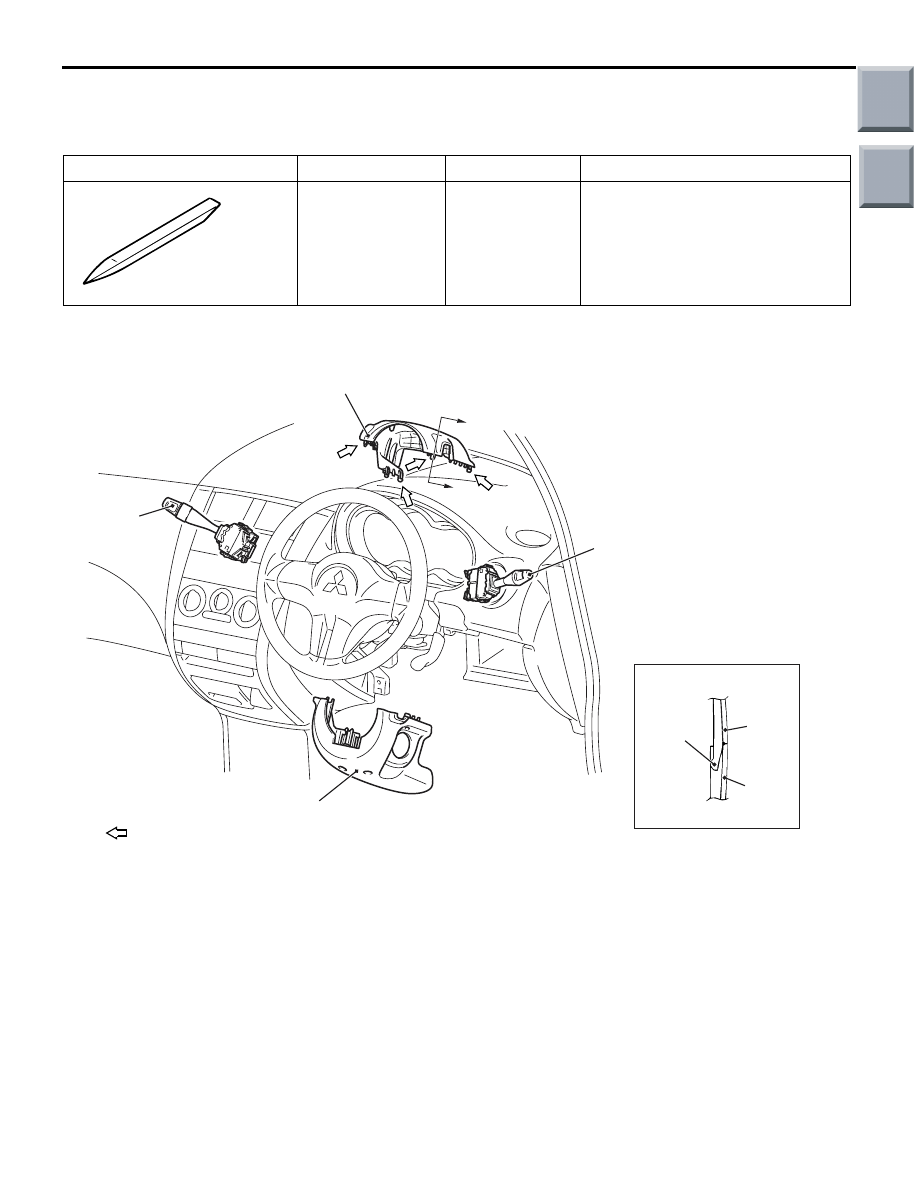
REMOVAL AND INSTALLATION

M1543009100606

AC207716AC

1

2

3

4

1

2

A

A

Section A-A

Claw

NOTE
       : Claw positions

Removal steps 

Steering wheel (Refer to GROUP 
37, Steering wheel 

P.37-90

.)

1.

Upper column cover

2.

Lower column cover

3.

Lighting switch

4.

Windshield wiper and washer 
switch

Removal steps (Continued)

Main

Index

Group

TOC

COLUMN SWITCH

CHASSIS ELECTRICAL

54A-90

INSPECTION

M1543019504607

LIGHTING SWITCH CONTINUITY CHECK

AC103138

Switch position

Tester 
connection 

Specified 
condition

OFF

Open 
circuit

Automatic lighting switch 3 

− 5

Continuity 
exists (2 

Ω 

or less)

Headlamp switch

− 6

Continuity 
exists (2 

Ω 

or less)

Tail lamp switch

− 7

Continuity 
exists (2 

Ω 

or less)

Passing switch

− 8

Continuity 
exists (2 

Ω 

or less)

Dimmer switch

− 9

Continuity 
exists (2 

Ω 

or less)

Turn-signal lamp switch 
(RH)

− 10

Continuity 
exists (2 

Ω 

or less)

Turn-signal lamp switch 
(LH)

− 11

Continuity 
exists (2 

Ω 

or less)

COLUMN SWITCH (SWITCH BODY) CON-
TINUITY CHECK

1. Remove the lighting switch, wiper and washer 

switch.

2. Check that there is continuity of each same termi-

nal number (from Nos. 3 to 11) between each 
connectors of column switch body left in the 
steering column. 

1

6

8

11

10

9

7

5

4

3

2

1

6

8

11

10

9

7

5

4

3

2

AC005499

At lighting 
switch side

At wiper/washer 
switch side

AE

Column switch 
body

Tester 
connection 

Specified 
condition

Lighting switch side 
connector
Wiper and washer 
switch side 
connector

− 3

− 4

− 5

− 6

− 7

− 8

− 9

10 

− 10

11 

− 11

Continuity 
exists (2 

Ω or 

less)

Main

Index

Group

TOC

RADIO AND CD PLAYER

CHASSIS ELECTRICAL

54A-91

RADIO AND CD PLAYER

SPECIAL TOOLS

M1542000602298

Tool

Number

Name

Application

MB990784

MB990784

Ornament remover

Removal of upper centre 
panel, consol panel, 
lower centre panel, 
heater control panel

MB991223

A

D

C

B

AZ

DO NOT USE

MB991223
A: MB991219
B: MB991220 
C: MB991221
D: MB991222

Harness set
A: Test harness
B: LED harness
C: LED harness 

adapter

D: Probe

For checking voltage 
(continuity and value) at 
harness and connectors

A: For checking 

connector pin contact 
voltage

B: For checking power 

supply circuits

C: For checking power 

supply circuits

D: For connection to 

commercially 
available tester

MB992006

MB992006

Extra fine probe

Continuity check and 
voltage measurement at 
harness wire or 
connector

TROUBLESHOOTING

TROUBLESHOOTING

M1544000700176

Use these steps to plan your diagnostic strategy. Fol-
low through with each step to ensure that you have 
exhausted all possible methods of finding an audio 
system fault.
1. Gather information from the customer.

2. Verify that the condition described by the 

customer exists.

3. Find the malfunction by following the Symptom 

Chart.

4. Verify that the malfunction is eliminated.

STANDARD FLOW OF DIAGNOSIS TROU-
BLESHOOTING

Refer to GROUP 00, How to Use Troubleshoot-
ing/Inspection Service Points 

P.00-5

.

Main

Index

Group

TOC

RADIO AND CD PLAYER

CHASSIS ELECTRICAL

54A-92

TROUBLE SYMPTOM CHART

M1544004900558

Symptom

Inspection 
Procedure No.

Reference 
Page

Power of radio and CD player does not turn ON when the ignition switch 
is in the "ACC" position or "ON" position.

1

P.54A-93

No sound from one speaker.

2

P.54A-95

Noise

Noise appears at certain places when travelling 
(AM).

3

P.54A-100

Noise ispresent while moving (FM).

4

P.54A-101

Mixed with noise, only at night (AM).

5

P.54A-102

Broadcasts can be heard but both AM and FM have 
a lot of noise.

6

P.54A-102

There is more noise on either AM or FM.

7

P.54A-103

There is noise when starting the engine.

8

P.54A-104

Some noise appears when there is vibration or 
shocks during travelling.

9

P.54A-105

Noise sometimes appears on FM during travelling.

10

P.54A-106

Ever-present noise.

11

P.54A-107

Radio

There is noise but no reception for both AM and FM 
or no sound from AM, or no sound from FM.

12

P.54A-107

Poor reception.

13

P.54A-108

Distortion on AM or on both AM and FM.

14

P.54A-109

Distortion on FM only.

15

P.54A-109

Using the auto select function, too few automatic 
stations are selected.

16

P.54A-110

Preset stations are erased.

17

P.54A-111

CD player

CD can not be inserted.

18

P.54A-114

No sound (CD only).

19

P.54A-114

CD sound skips.

20

P.54A-115

Sound quality is poor.

21

P.54A-115

CD cannot be ejected.

22

P.54A-116

Main

Index

Group

TOC


Content   ..  484  485  486  487   ..