Mitsubishi Colt Ralliart. Manual - part 424


  Index      Mitsubishi     Mitsubishi Colt Ralliart - service repair manual


Search            


Content   ..  422  423  424  425   ..


Mitsubishi Colt Ralliart. Manual - part 424


INPUT SIGNAL PROCEDURES

SMART WIRING SYSTEM (SWS) USING SWS MONITOR

54C-204

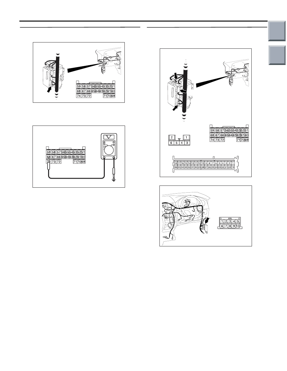
Step 2. Voltage measurement at the B-133 
ETACS-ECU connector.

(1) Remove the ETACS-ECU, and measure at the 

junction block side.

(2) Ignition switch: ON position

(3) Voltage between B-133 ETACS-ECU connector 

terminal No.68 and body earth

OK: System voltage

Q: Is the check result normal?

YES : 

Go to Step 4.

NO : 

Go to Step 3.

Step 3. Check the wiring harness between B-133 
ETACS-ECU connector terminal No.68 to the 
ignition switch (IG1).

NOTE: 

Prior to the wiring harness inspection, check joint 
connector B-22 and junction block connector B-129 
and B-131, and repair if necessary.

• Check the power supply line for open circuit.

Q: Is the check result normal?

YES : 

The trouble can be an intermittent 

malfunction (Refer to GROUP 00 

− How to 

use Troubleshooting/inspection Service 
Points 

− How to Cope with Intermittent 

Malfunction 

P.00-13

).

NO : 

Repair the wiring harness.

AC313826AC

B-133 (GR)

Connector: B-133

Harness side

Junction block (Rear view)

AC310507 ET

Connector B-133 
(Harness side)

AC313827AB

B-131

B-131

B-129

B-133 (GR)

B-133

B-129

Connectors: B-129, B-131, B-133

Junction block (Rear view)

Harness side

Harness side

Harness side

AC401055

Connector: B-22

AD

Main

Index

Group

TOC

INPUT SIGNAL PROCEDURES

SMART WIRING SYSTEM (SWS) USING SWS MONITOR

54C-205

Step 4. SWS monitor data list.
Check the input signal from the ignition switch.

<Selected item> ETACS ECU

• Ignition switch: ACC → ON

OK: Normal condition is displayed.

Q: Is the check result normal?

YES : 

The trouble can be an intermittent 

malfunction (Refer to GROUP 00 

− How to 

use Troubleshooting/inspection Service 
Points 

− How to Cope with Intermittent 

Malfunction 

P.00-13

).

NO : 

Replace the ETACS-ECU.

Inspection Procedure N-3: The driver's door switch signal is not received.

CAUTION

Whenever the ECU is replaced, ensure that the 
input signal circuit is normal.

Item No.

Item name

Normal 
condition

Item 30

IG SW(IG1)

from OFF to ON

ETACS-
ECU

DOOR SWITCH 
(FRONT: RH)

Wire colour code
B : Black     LG : Light green     G : Green     L : Blue     W : White     Y : Yellow     SB : Sky blue
BR : Brown     O : Orange     GR : Gray     R : Red     P : Pink     V : Violet

Driver's Door Switch Input Circuit

Main

Index

Group

TOC

INPUT SIGNAL PROCEDURES

SMART WIRING SYSTEM (SWS) USING SWS MONITOR

54C-206

COMMENTS ON TROUBLE SYMPTOM

Input signal from the driver's door switch is used to 
operate the functions below. If the signal is abnormal, 
these functions will not work normally.

• Lamp reminder buzzer

• Keyless entry system

• Power window timer

• Ignition key cylinder illumination lamp

• Door-ajar warning lamp

POSSIBLE CAUSES

• Malfunction of the driver's door switch

• Malfunction of the ETACS-ECU

• Damaged harness wires and connectors

DIAGNOSIS PROCEDURE

Step 1. Check the installation condition.
Check that the front door switch (RH) is installed on 
the body correctly.

Q: Is the check result normal?

YES : 

Go to Step 2.

NO : 

Correct the installation condition.

Step 2. Connector check: C-29 front door switch 
(RH) connector.

Q: Is the check result normal?

YES : 

Go to Step 3.

NO : 

Repair the defective connector.

Step 3. Check the front door switch (RH).
Refer to GROUP 42 

− Door 

P.42-39

.

Q: Is the check result normal?

YES : 

Go to Step 4.

NO : 

Replace the front door switch (RH).

Step 4. Connector check: B-133 ETACS-ECU 
connector.

Q: Is the check result normal?

YES : 

Go to Step 5.

NO : 

Repair the defective connector.

AC401057

AF

Connector: C-29

Harness side

AC313826AC

B-133 (GR)

Connector: B-133

Harness side

Junction block (Rear view)

Main

Index

Group

TOC

INPUT SIGNAL PROCEDURES

SMART WIRING SYSTEM (SWS) USING SWS MONITOR

54C-207

Step 5. Check the wiring harness between C-29 
front door switch (RH) connector terminal No.1 to 
B-133 ETACS-ECU connector terminal No.51.

NOTE: 

Prior to the wiring harness inspection, check joint 
connector B-23 and B-24, and repair if necessary.

• Check the input line for open circuit.

Q: Is the check result normal?

YES : 

Go to Step 6.

NO : 

Repair the wiring harness.

Step 6. SWS monitor data list
Check the input signal from the driver's door switch.

<Selected item> ETACS ECU

• Driver's door: close → open

OK: Normal condition is displayed.

Q: Is the check result normal?

YES : 

The trouble can be an intermittent 

malfunction (Refer to GROUP 00 

− How to 

use Troubleshooting/inspection Service 
Points 

− How to Cope with Intermittent 

Malfunction 

P.00-13

).

NO : 

Replace the ETACS-ECU.

AC401057

AF

Connector: C-29

Harness side

AC313826AC

B-133 (GR)

Connector: B-133

Harness side

Junction block (Rear view)

AC401056

Connectors: B-23, B-24

AC

B-23

B-24

B-24

B-23

Item No.

Item name

Normal 
condition

Item 32

DR DOOR SW

from OFF to 
ON

Main

Index

Group

TOC


Content   ..  422  423  424  425   ..