Mitsubishi Colt Ralliart. Manual - part 423
SYMPTOM PROCEDURES
SMART WIRING SYSTEM (SWS) USING SWS MONITOR
54C-200
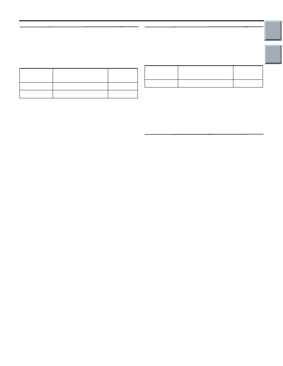
Step 4. SWS monitor data list
Check the SWS communication signal, which is
related to the door-ajar warning lamp.
<Selected item> ETACS ECU
• Ignition switch: ON position
• Driver's door: open
OK: Normal conditions are displayed for all
the items.
Q: Is the check result normal?
Normal conditions are displayed for all the items. :
Go to Step 5.
Normal condition is not displayed for item No.30. :
Refer to inspection procedure N-2 "The
ignition switch (IG1) signal is not received
."
Normal condition is not displayed for item No.32. :
Refer to inspection procedure N-3 "The
driver's door switch signal is not received
."
Step 5. ETACS switch data by using the SWS
monitor
Check the ETACS-ECU input signal related to the
door-ajar warning buzzer function.
• Doors other than the driver's door (including the
tailgate): Closed to open
OK: Normal condition is displayed.
Q: Is the check result normal?
YES :
Go to Step 6.
NO :
Refer to inspection procedure N-10 "All the
door switch signals are not received
."
Step 6. M.U.T.-III actuator test
Perform the actuator test for the combination meter,
and check that the door-ajar warning lamp illumi-
nates (Refer to GROUP 54A
− Combination Meter
Q: Is the check result normal?
YES :
Replace the ETACS-ECU.
NO :
Replace the combination meter.
Item No.
Item name
Normal
condition
Item 30
IG SW(IG1)
ON
Item 32
DR DOOR SW
ON
Item No.
Item name
Normal
condition
Item 40
ALL DOOR SW
ON
Main
Index
Group
TOC