Mitsubishi Colt Ralliart. Manual - part 422


  Index      Mitsubishi     Mitsubishi Colt Ralliart - service repair manual


Search            


Content   ..  420  421  422  423   ..


Mitsubishi Colt Ralliart. Manual - part 422


SYMPTOM PROCEDURES

SMART WIRING SYSTEM (SWS) USING SWS MONITOR

54C-196

COMMENTS ON TROUBLE SYMPTOM

If the luggage compartment lamp do not illuminate, 
the wiring harness connector(s), the bulb or the fuse 
may be defective or burned out.

POSSIBLE CAUSES

• Malfunction of the luggage compartment lamp

• Damaged harness wires and connectors

Step 1. Check if the room lamp illuminates.
Check whether the room lamp illuminates normally.

Q: Is the check result normal?

YES : 

Go to Step 2.

NO : 

Refer to Inspection Procedure M-1 "The 
interior lamps (room ramp, luggage 
compartment lamp) does not illuminate or 
extinguish normally 

P.54C-186

."

Step 2. Connector check: C-11 luggage 
compartment lamp connector

Q: Is the check result normal?

YES : 

Go to Step 3.

NO : 

Repair the defective connector.

Step 3. Check the bulb.
Check that the luggage compartment lamp bulb is 
not blown.

Q: Is the check result normal?

YES : 

Go to Step 4.

NO : 

Replace the luggage compartment lamp 
bulb.

Step 4. Check the luggage compartment lamp.
Check whether the luggage compartment lamp illu-
minates normally.

Q: Is the check result normal?

YES : 

Go to Step 5.

NO : 

Replace the luggage compartment lamp.

Step 5. Determine a trouble spot.

Q: Which switch position (DOOR or ON) does the 

luggage compartment lamp illuminate at? 
The lamp illuminates at neither the ON nor DOOR 
position.  : 

Go to Step 6.

The lamp illuminates at the DOOR position. : 

Go to 

Step 7.

The lamp illuminates at the ON position. : 

Go to 

Step 9.

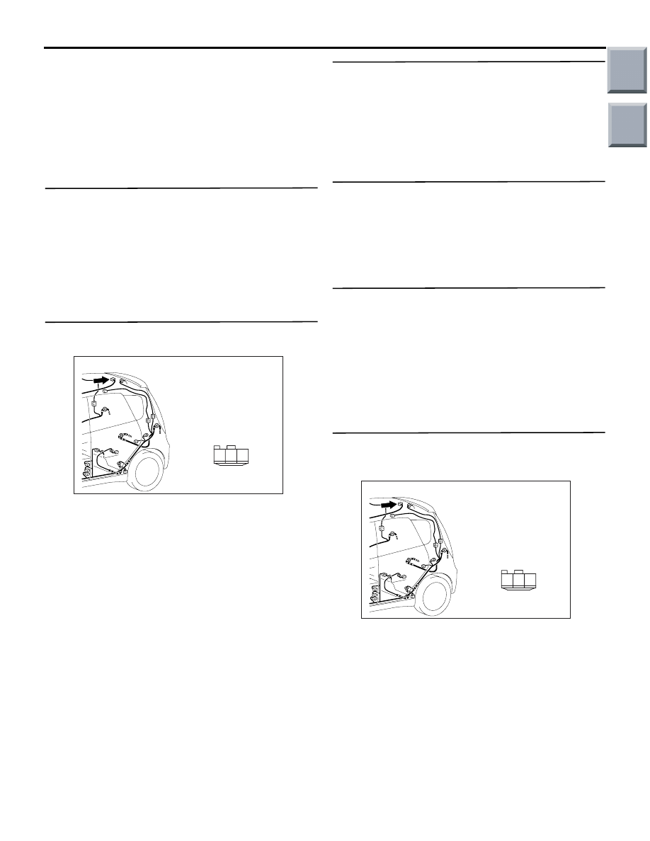
Step 6. Check the wiring harness from C-11 
luggage compartment lamp connector terminal 
No.3 to fusible link (1).

AC401059

Connector: C-11

Harness side

AD

3

1

2

AC401059

Connector: C-11

Harness side

AD

3

1

2

Main

Index

Group

TOC

SYMPTOM PROCEDURES

SMART WIRING SYSTEM (SWS) USING SWS MONITOR

54C-197

NOTE: 

Prior to the wiring harness inspection, check interme-
diate connector C-02 and junction block connector 
B-108 and B-113 repair if necessary.

• Check the power supply line for open circuit.

Q: Is the check result normal?

YES : 

The trouble can be an intermittent 

malfunction (Refer to GROUP 00 

− How to 

use Troubleshooting/inspection Service 
Points 

− How to Cope with Intermittent 

Malfunction 

P.00-13

).

NO : 

Repair the wiring harness.

Step 7. Connector check: B-134 ETACS-ECU 
connector

Q: Is the check result normal?

YES : 

Go to Step 8.

NO : 

Repair the defective connector.

Step 8. Check the wiring harness from B-134 
ETACS-ECU connector terminal No.18 to C-11 
luggage compartment lamp connector terminal 
No.1

AC401057

Connector: C-02

AD

AC313825 AB

Connectors: B-108, B-113

Junction Block (Front view)

B-113

B-108 (B)

Harness side

B-108

Harness side

B-113

AC313826

Connector: B-134

AG

Junction block side

Junction block (Rear view)

AC313826

Connector: B-134

AG

Junction block side

Junction block (Rear view)

AC401059

Connector: C-11

Harness side

AD

3

1

2

Main

Index

Group

TOC

SYMPTOM PROCEDURES

SMART WIRING SYSTEM (SWS) USING SWS MONITOR

54C-198

NOTE: 

Prior to the wiring harness inspection, check interme-
diate connector C-02 and junction block connector 
B-113 repair if necessary.

• Check the input and output lines for open circuit.

Q: Is the check result normal?

YES : 

The trouble can be an intermittent 

malfunction (Refer to GROUP 00 

− How to 

use Troubleshooting/inspection Service 
Points 

− How to Cope with Intermittent 

Malfunction 

P.00-13

).

NO : 

Repair the wiring harness.

Step 9. Check the wiring harness from C-11 
luggage compartment lamp connector terminal 
No.2 to body earth.

NOTE: 

Prior to the wiring harness inspection, check interme-
diate connector C-02 and junction block connector 
B-113 and B-130 repair if necessary.

• Check the earth wires for open circuit.

Q: Is the check result normal?

YES : 

The trouble can be an intermittent 

malfunction (Refer to GROUP 00 

− How to 

use Troubleshooting/inspection Service 
Points 

− How to Cope with Intermittent 

Malfunction 

P.00-13

).

NO : 

Repair the wiring harness.

AC401057

Connector: C-02

AD

AC313824

Harness side

AB

Connector: B-113

Junction block (Front view)

AC401059

Connector: C-11

Harness side

AD

3

1

2

AC401057

Connector: C-02

AD

AC313824

Harness side

AB

Connector: B-113

Junction block (Front view)

AC313826

Harness side

AE

Connector: B-130

Junction block (Rear view)

Main

Index

Group

TOC

SYMPTOM PROCEDURES

SMART WIRING SYSTEM (SWS) USING SWS MONITOR

54C-199

INSPECTION PROCEDURE M-4: The door-ajar warning lamp does not illuminate/extinguish normally.

CAUTION

Whenever the ECU is replaced, ensure that the 
input and output signal circuits are normal.

COMMENTS ON TROUBLE SYMPTOM

If the door-ajar warning lamp does not work normally, 
the input signal circuit or the ETACS-ECU may be 
defective.

POSSIBLE CAUSES

• Malfunction of the all door switches

• Malfunction of the combination meter

• Malfunction of the CAN bus line

• Malfunction of the ETACS-ECU

• Damaged harness wires and connectors

DIAGNOSIS PROCEDURE

Step 1. M.U.T.-III CAN bus diagnostics
Use the M.U.T.-III to diagnose the CAN bus lines.

Q: Is the check result normal?

YES : 

Go to Step 2.

NO : 

Repair the CAN bus line (Refer to GROUP 
54D, Diagnosis 

P.54D-13

).

Step 2. M.U.T.-III other system diagnosis code
Check whether the combination meter-related diag-
nosis code is set.

Q: Is the diagnosis code set?

YES : 

Diagnose the combination meter (Refer to 

GROUP 54A 

− Troubleshooting 

P.54A-31

).

NO : 

Go to Step3.

Step 3. ECU check by using the SWS monitor
Check that the power supply and earth lines to the 
ETACS-ECU and the SWS communication lines are 
normal.

• Ignition switch: OFF

ECU TO BE CHECKED

• ETACS ECU

OK: "OK" is displayed on the "ETACS ECU" 
menu.

Q: Is the check result normal?

YES : 

Go to Step 4.

NO : 

Refer to Inspection Procedure A-3 
"Communication with the ETACS-ECU is 
not possible 

P.54C-41

."

ETACS-
ECU

SPEED SIGNAL

COMBINATION
METER

CAN COMMUNICATION LINE
(CAN_L LINE)

CAN COMMUNICATION LINE
(CAN_H LINE)

INPUT SIGNAL

INPUT SIGNAL

· IGNITION SWITCH (IG1)
· ALL DOOR SWITCH
· TAILGATE SWITCH

Door-Ajar Warning Lamp Function

Main

Index

Group

TOC


Content   ..  420  421  422  423   ..