Mitsubishi Colt Ralliart. Manual - part 344
SYMPTOM PROCEDURES
SMART WIRING SYSTEM (SWS) NOT USING SWS MONITOR
54B-120
Step 2. Pulse check
Check the input signals below which are related to
the rear washer.
• Ignition switch: ACC
OK: The M.U.T.-III sounds or the voltmeter
needle fluctuates.
Q: Is the check result normal?
YES :
Go to Step 3.
NO :
Refer to Inspection Procedure N-5 "The
column switch (windshield wiper washer
and rear wiper washer switch) signal is not
received
."
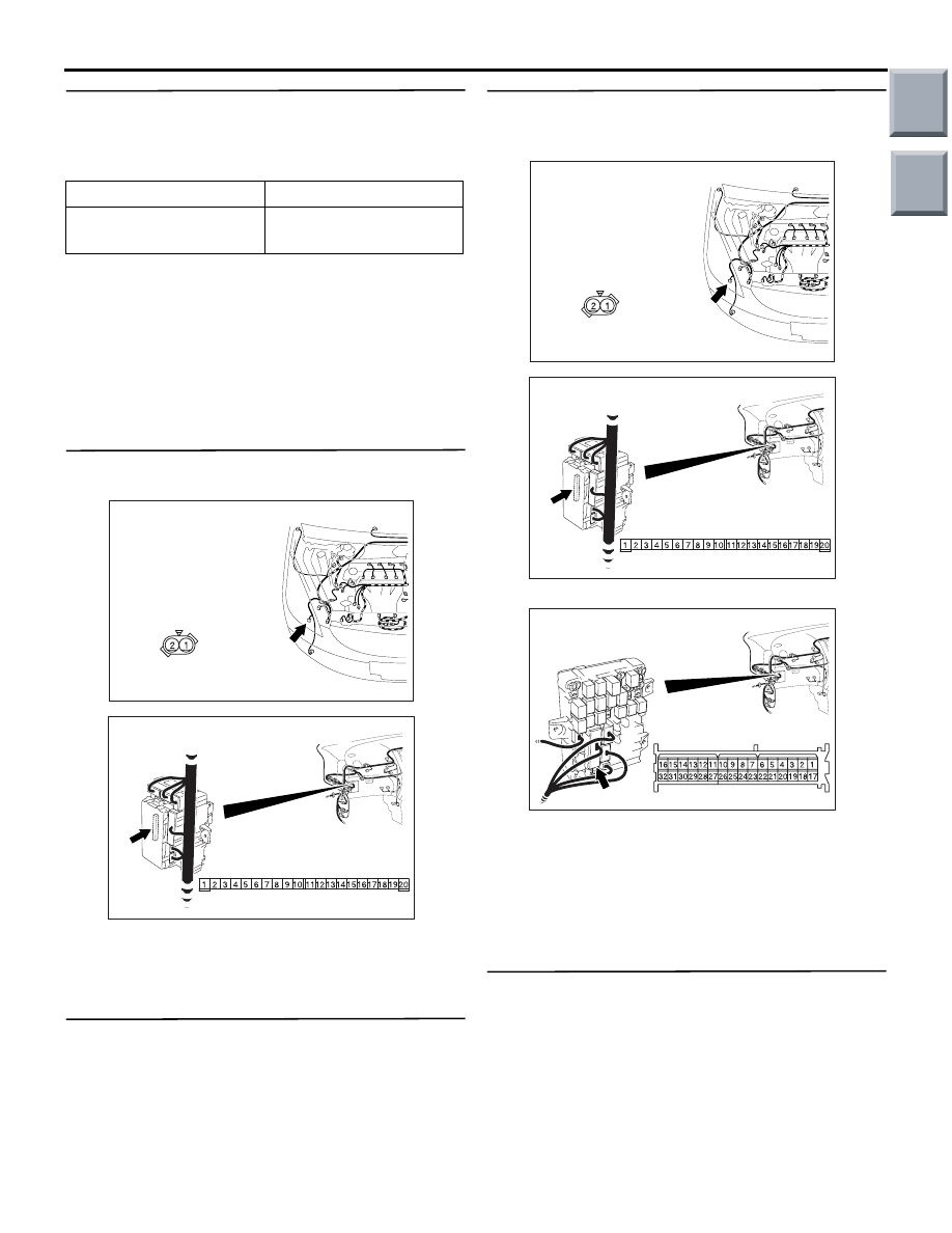
Step 3. Connector check: A-35 washer motor
connector and B-134 ETACS-ECU connector.
Q: Is the check result normal?
YES :
Go to Step 4.
NO :
Repair the connector.
Step 4. Check the washer motor.
Refer to GROUP 51
− Rear wiper and washer
Q: Is the check result normal?
YES :
Go to Step 5.
NO :
Replace the washer motor.
Step 5. Check the wiring harness between B-134
ETACS-ECU connector terminal Nos.12, 9 to A-35
washer motor connector terminal No.1, 2.
NOTE:
Prior to the wiring harness inspection, check junction
block connector B-112, and repair if necessary.
• Check the output signal line.
Q: Is the check result normal?
YES :
Go to Step 6.
NO :
Repair the wiring harness.
Step 6. Retest the system.
Check that the rear washer works normally.
Q: Is the check result satisfactory?
YES :
The trouble can be an intermittent
malfunction (Refer to GROUP 00
− How to
use Troubleshooting/inspection Service
Points
− How to Cope with Intermittent
).
NO :
Replace the ETACS-ECU.
System switch
Check condition
Column switch (rear
washer switch)
When the switch is
turned from off to on
AC509176
Connector: A-35
Harness side
AB
AC313872 AH
Connector: B-134
Harness side
Junction block (Rear view)
AC509176
Connector: A-35
Harness side
AB
AC313872 AH
Connector: B-134
Harness side
Junction block (Rear view)
AC313870
Connector: B-112
BE
Junction block (Front view)
Harness side
Main
Index
Group
TOC