Mitsubishi Colt Ralliart. Manual - part 312
AC313937AT
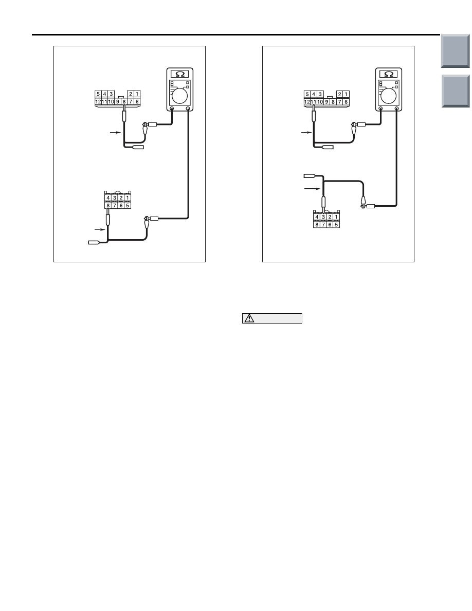
Harness side: B-01
Harness side: B-37
Test
harness
Test
harness
TROUBLESHOOTING
CONTROLLER AREA NETWORK (CAN)
54D-77
(4) Continuity between B-01 joint connector (CAN2)
terminal No.8 and B-37 EPS-ECU connector
terminal No.8
OK: Continuity (2
Ω or less)
AC313937AU
Harness side: B-01
Harness side: B-37
Test
harness
Test
harness
(5) Continuity between B-01 joint connector (CAN2)
terminal No.11 and B-37 EPS-ECU connector
terminal No.3
OK: Continuity (2
Ω or less)
CAUTION
Strictly observe the specified wiring harness
repair procedure. For details refer to
Q: Is the check result normal?
YES :
<All the resistances measure 2
Ω or less>
Power supply to the EPS-ECU may be
suspected. Diagnose the EPS. Refer to
GROUP 37
− Troubleshooting
.
NO :
<Either or all of the resistances measure
more than 2
Ω> Repair the wiring harness
between the joint connector (CAN2) and the
EPS-ECU connector.
Main
Index
Group
TOC