Mitsubishi Colt Ralliart. Manual - part 313


  Index      Mitsubishi     Mitsubishi Colt Ralliart - service repair manual


Search            


Content   ..  311  312  313  314   ..


Mitsubishi Colt Ralliart. Manual - part 313


TROUBLESHOOTING

CONTROLLER AREA NETWORK (CAN)

54D-81

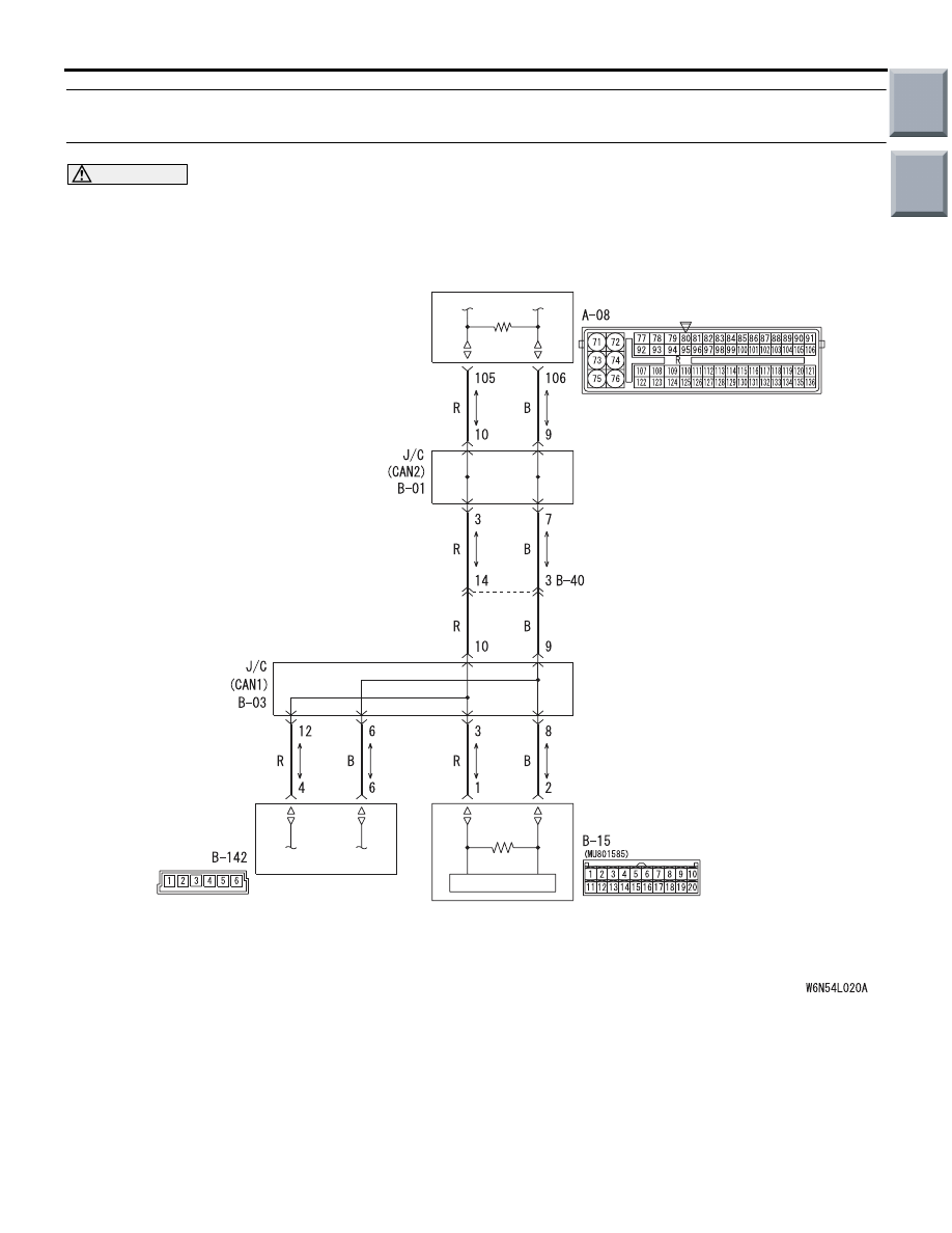
Diagnostic Item 12: Diagnose when the M.U.T.-III cannot receive the data sent by steering wheel 
sensor.

CAUTION

When servicing a CAN bus line, earth yourself by touching a metal object such as an unpainted water 
pipe. If you fail to do, a component connected to the CAN bus line may be broken.

STEERING
WHEEL
SENSOR

COMBINATION
METER

ENGINE-ECU

Wire colour code
B : Black     LG : Light green     G : Green     L : Blue     W : White     Y : Yellow     SB : Sky blue
BR : Brown     O : Orange     GR : Grey     R : Red     P : Pink     V : Violet     PU : Purple

FUNCTION

The diagnostic result demonstrates that "Diagnose 
when the M.U.T.-III cannot receive the data sent by 
steering wheel sensor" when the M.U.T.-III checks 
the periodically sent data from each ECU and cannot 
receive the steering wheel sensor data only.

TROUBLE JUDGEMENT CONDITIONS

M.U.T.-III judges the trouble when the periodically 
sent data from steering wheel sensor cannot be 
received and sent. 

Main

Index

Group

TOC

TROUBLESHOOTING

CONTROLLER AREA NETWORK (CAN)

54D-82

PROBABLE CAUSES

• Damaged harness wires and connectors

• Power supply circuit malfunction of the steering 

wheel sensor

• Malfunction of the steering wheel sensor

DIAGNOSIS PROCEDURE

STEP 1. Connector check: B-03 joint connector 
(CAN1) and B-142 steering wheel sensor 
connector

AC313820

Connector: B-03

AE

AC601077AB

Connector: B-142

Harness side

CAUTION

The strand end of the twist wire should be within 
10 cm from the connector. For details refer to 

P.54D-5

.

When checking the joint connector, ensure that its 
wiring harness side and its short pins are not dam-
aged.

Q: Is the check result normal?

YES : 

Go to Step 2.

NO : 

Repair the defective connector. Replace the 
joint connector as necessary.

STEP 2. Resistance measurement at B-03 joint 
connector (CAN1) and B-142 steering wheel 
sensor connector.

CAUTION

A digital multimeter should be used. For details 
refer to 

P.54D-5

.

CAUTION

The test wiring harness should be used. For 
details refer to 

P.54D-5

.

AC313820

Connector: B-03

AE

AC601077AB

Connector: B-142

Harness side

(1) Disconnect the joint connector (CAN1) and the 

steering wheel sensor connector, and measure at 
the wiring harness side.

(2) Turn the ignition switch to the OFF (LOCK) 

position.

CAUTION

When measuring the resistance, disconnect the 
negative battery terminal. For details refer to 

P.54D-5

.

(3) Ensure that the negative battery terminal is 

disconnected.

Main

Index

Group

TOC

AC204740

AC204740

AC204740

AC204740

AC204740

AC204740JE

Harness side: B-142

Harness side: B-03

Test 
harness

Test 
harness

TROUBLESHOOTING

CONTROLLER AREA NETWORK (CAN)

54D-83

(4) Continuity between B-03 joint connector (CAN1) 

terminal No.6 and B-142 steering wheel sensor 
connector terminal No.6

OK: Continuity (2 

 or less) 

AC204740JF

Harness side: B-142

Harness side: B-03

Test 
harness

Test 
harness

(5) Continuity between B-03 joint connector (CAN1) 

terminal No.12 and B-142 steering wheel sensor 
connector terminal No.4

OK: Continuity (2 

 or less) 

CAUTION

Strictly observe the specified wiring harness 
repair procedure. For details refer to 

P.54D-5

.

Q: Is the check result normal?

YES : 

<All the resistances measure 2 

Ω or less> 

Power supply to the steering wheel sensor 
may be suspected. Diagnose the ASC 
system. Refer to GROUP 35C 

− 

Troubleshooting 

P.35C-102

.

NO  : 

<Either or all of the resistances measure 
more than 2 

Ω> Repair the wiring harness 

between joint connector (CAN1) and the 
steering wheel sensor connector.

Main

Index

Group

TOC

CAN COMMUNICATION-RELATED DIAGNOSIS CODE (U CODE) TABLE

CONTROLLER AREA NETWORK (CAN)

54D-84

CAN COMMUNICATION-RELATED DIAGNOSIS CODE 

(U CODE) TABLE

M1548300300450

Output 
ECU

Code No. Diagnostic item

Action

Engine-E
CU 
<M/T> or 
engine-C
VT-ECU 
<CVT>

U1073

Bus Off

CAN main bus line diagnosis

U1102

ABS-ECU <vehicles without ASC> or 
ASC-ECU <vehicles with ASC> time-out

U1106

EPS-ECU time-out

U1108

Meter-A/C-ECU time-out (related to 
meter)

U1110

Meter-A/C-ECU time-out (related to A/C)

ABS-EC

<vehicle
s without 
ASC>

U1073

Bus Off

CAN main bus line diagnosis

ASC-EC

<vehicle
s with 
ASC>

U1073

Bus Off

CAN main bus line diagnosis

U1100

engine-ECU <M/T> or engine-CVT-ECU 
<CVT> time-out (related to engine)

U1104

Steering wheel sensor time-out

U1105

G and yaw rate sensor time-out

EPS-EC
U

U1073

Bus Off

CAN main bus line diagnosis

U1100

engine-ECU <M/T> or engine-CVT-ECU 
<CVT> time-out (related to engine)

U1102

ABS-ECU <vehicles without ASC> or 
ASC-ECU <vehicles with ASC> time-out

U1120

Failure information on engine-ECU <M/T> 
or engine-CVT-ECU <CVT> (related to 
engine)

Diagnose CAN main bus lines and 
confirm input signals.

U1122

Failure information on ABS-ECU 
<vehicles without ASC> or ASC-ECU 
<vehicles with ASC>

Meter-A/
C-ECU

U1073

Bus Off

CAN main bus line diagnosis

U1100

engine-ECU <M/T> or engine-CVT-ECU 
<CVT> time-out (related to engine)

U1101

engine-ECU <M/T> or engine-CVT-ECU 
<CVT> time-out (related to CVT)

U1102

ABS-ECU <vehicles without ASC> or 
ASC-ECU <vehicles with ASC> time-out

U1106

EPS-ECU time-out

U1109

ETACS-ECU time-out

U1120

Failure information on engine-ECU <M/T> 
or engine-CVT-ECU <CVT> (related to 
engine)

Diagnose CAN main bus lines and 
confirm input signals.

Main

Index

Group

TOC


Content   ..  311  312  313  314   ..