Mitsubishi Colt Ralliart. Manual - part 305
TROUBLESHOOTING
CONTROLLER AREA NETWORK (CAN)
54D-49
FUNCTION
The M.U.T.-III judges a short between CAN_H and
CAN_L line when all data from ECU cannot be
received while checking periodically sent data from
each ECU even if the voltage is normal.
TROUBLE JUDGEMENT CONDITIONS
The M.U.T.-III judges the trouble when it is impossi-
ble to send and receive the all ECU periodically sent
data and the voltage of CAN_H and CAN_L line is
4.0 volts or less and 1.0 volt or more.
POSSIBLE CAUSES
• Malfunction of the wiring harness
• Malfunction of the connector
• Malfunction of each ECU
DIAGNOSIS PROCEDURE
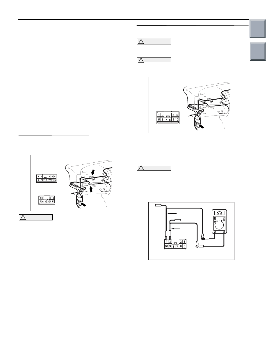
STEP 1. Connector check: B-01 joint connector
(CAN2), B-03 joint connector (CAN1), B-40
intermediate connector
AC313820
Connectors: B-01, B-03, B-40
B-40
B-40
AN
B-01
B-03
B-01, B-03
CAUTION
The strand end of the twist wire should be within
10 cm from the connector. For details refer to
.
When checking the joint connector, ensure that its
wiring harness side and its short pins are not dam-
aged.
Q: Is the check result normal?
YES :
Go to Step 2.
NO :
Repair the defective connector.
STEP 2. Resistance measurement at the B-40
intermediate connector.
CAUTION
A digital multimeter should be used. For details
refer to
CAUTION
The test wiring harness should be used. For
details refer to
.
AC313820
Connector: B-40
AD
(1) Disconnect the connector, and measure at its
female-side intermediate connector (at the front
wiring harness side).
(2) Turn the ignition switch to the OFF (LOCK)
position.
CAUTION
When measuring the resistance, disconnect the
negative battery terminal. For details refer to
.
(3) Ensure that the negative battery terminal is
disconnected.
AC313936 AB
Female side: B-40
Test
harness
Test
harness
(4) Resistance between B-40 intermediate connector
terminal Nos.3 and 4
OK: 120
± 20 Ω
Q: Is the check result normal?
YES :
<Within 120
± 20 Ω> Go to Step 3.
NO :
<Not within 120
± 20 Ω>Go to Step 7.
Main
Index
Group
TOC