Mitsubishi Colt Ralliart. Manual - part 303


  Index      Mitsubishi     Mitsubishi Colt Ralliart - service repair manual


Search            


Content   ..  301  302  303  304   ..


Mitsubishi Colt Ralliart. Manual - part 303


AC206268AJ

<Vehicles without ASC>

METER/AC

ETACS

M.U.T.

J/C(1)

J/C(2)

ABS

EPS

ENG/CVT

: Red section on screen

AC206268AK

<Vehicles with ASC>

METER/AC

ETACS

SAS

M.U.T.

J/C(1)

J/C(2)

ASC

EPS

YR/G

ENG/CVT

: Red section on screen

TROUBLESHOOTING

CONTROLLER AREA NETWORK (CAN)

54D-41

(2) Check that the M.U.T.-III indications correspond 

to the illustration.

Q: Is the check result normal?

YES : 

<M.U.T.-III indications correspond to the 

illustration> Repair the wiring harness 
between joint connector (CAN1) and 
ETACS-ECU connector.

NO : 

<M.U.T.-III indications do not correspond to 
the illustration> Check the ETACS-ECU 
connector, and repair if necessary. If the 
ETACS-ECU connector is in good condition, 
power supply to the ETACS-ECU may be 
suspected. Diagnose the SWS system. 
Refer to GROUP 54B 

− Troubleshooting 

P.54B-43

.

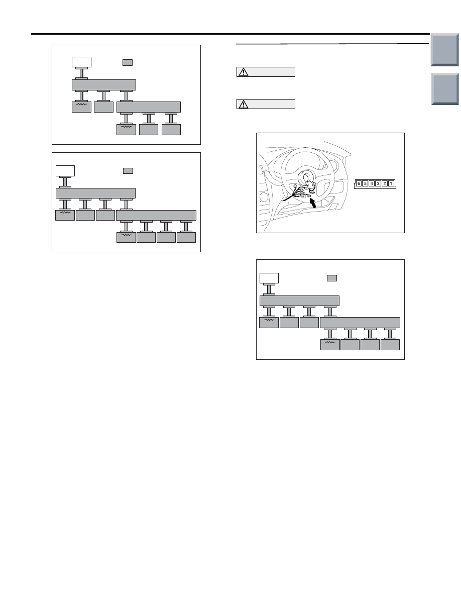
STEP 5. M.U.T.-III CAN bus diagnostics (B-142 
steering wheel sensor connector disconnected) 

CAUTION

A digital multimeter should be used. For details 
refer to 

P.54D-5

.

CAUTION

The test wiring harness should be used. For 
details refer to 

P.54D-5

.

AC601077AB

Connector: B-142

Harness side

(1) Disconnect the steering wheel sensor connector, 

and diagnose by using the M.U.T.-III.

AC206268AK

<Vehicles with ASC>

METER/AC

ETACS

SAS

M.U.T.

J/C(1)

J/C(2)

ASC

EPS

YR/G

ENG/CVT

: Red section on screen

(2) Check that the M.U.T.-III indications correspond 

to the illustration.

Q: Is the check result normal?

YES : 

<M.U.T.-III indications correspond to the 

illustration> Repair the wiring harness 
between joint connector (CAN1) and 
steering wheel sensor connector.

NO : 

<M.U.T.-III indications do not correspond to 
the illustration> Check the steering wheel 
sensor connector, and repair if necessary. If 
the steering wheel sensor connector is in 
good condition, power supply to the steering 
wheel sensor may be suspected. Diagnose 
the ASC system. Refer to GROUP 35C 

− 

Troubleshooting 

P.35C-102

.

Main

Index

Group

TOC

TROUBLESHOOTING

CONTROLLER AREA NETWORK (CAN)

54D-42

STEP 6. Resistance measurement at the B-01 
joint connector (CAN2).

CAUTION

A digital multimeter should be used. For details 
refer to 

P.54D-5

.

CAUTION

The test wiring harness should be used. For 
details refer to 

P.54D-5

.

AC313820AF

Connector: B-01

(1) Disconnect the connector, and measure at the 

wiring harness side.

CAUTION

When measuring the resistance, disconnect the 
negative battery terminal. For details refer to 

P.54D-5

.

(2) Ensure that the negative battery terminal is 

disconnected.

(3) Measure the voltage between each of B-01 joint 

connector (CAN2) terminals and body earth.

<CAN_H>

AC204738HN

Harness side: B-01

Test 
harness

TerminalNo.1 and body earth <vehicles with 

ASC>

AC313908

AC313908AO

Harness side: B-01

Test 
harness

Terminal No.2 and body earth

AC313908

AC313908AS

Harness side: B-01

Test 
harness

Terminal No.8 and body earth

AC313908

AC313908AT

Harness side: B-01

Test 
harness

Terminal No.9 and body earth

OK: 1 k

 or more

Main

Index

Group

TOC

TROUBLESHOOTING

CONTROLLER AREA NETWORK (CAN)

54D-43

<CAN_L>

AC313908

AC313908AQ

Harness side: B-01

Test 
harness

Terminal No.4 and body earth

AC204738

AC204738

AC204738NG

Harness side: B-01

Test harness

Terminal No.5 and body earth <vehicles with 

ASC>

AC313908

AC313908AU

Harness side: B-01

Test 
harness

Terminal No.10 and body earth

AC313908

AC313908AV

Harness side: B-01

Test 
harness

Terminal No.11 and body earth

OK: 1 k

 or more

Q: Is the check result normal?

YES <all of the measurement results show 1 k

 or 

more> : 

Repair the wiring harness between joint 

connector (CAN2) and intermediate 
connector (B-40).

NO <The resistance between terminal No.1 or 5 and 
body earth is less than 1 k

> : 

Go to Step 9.

NO <The resistance between terminal No.2 or 4 and 
body earth is less than 1 k

> : 

Go to Step 7.

NO <The resistance between terminal No.8 or 11 
and body earth is less than 1 k

> : 

Go to Step 8.

NO <The resistance between terminal No.9 or 10 
and body earth is less than 1 k

> : 

Repair the 

wiring harness between joint connector 
(CAN2) and engine-ECU <M/T> or 
engine-CVT-ECU <CVT>.

STEP 7. M.U.T.-III CAN bus diagnostics (A-05 
ABS-ECU <vehicles without ASC> or ASC-ECU 
<vehicles with ASC> connector disconnected) 

AC601294

A-05 (B)

AB

Harness side

<ABS-ECU>

<ASC-ECU>

Connector: A-05

(1) Disconnect the ABS-ECU <vehicles without 

ASC> or ASC-ECU <vehicles with ASC> 
connector, and diagnose by using the M.U.T.-III.

Main

Index

Group

TOC

AC206268AJ

<Vehicles without ASC>

METER/AC

ETACS

M.U.T.

J/C(1)

J/C(2)

ABS

EPS

ENG/CVT

: Red section on screen

AC206268AK

<Vehicles with ASC>

METER/AC

ETACS

SAS

M.U.T.

J/C(1)

J/C(2)

ASC

EPS

YR/G

ENG/CVT

: Red section on screen

TROUBLESHOOTING

CONTROLLER AREA NETWORK (CAN)

54D-44

(2) Check that the M.U.T.-III indications correspond 

to the illustration.

Q: Is the check result normal?

YES : 

<M.U.T.-III indications correspond to the 

illustration> Repair the wiring harness 
between joint connector (CAN2) and 
ABS-ECU <vehicles without ASC> or 
ASC-ECU < connector.

NO : 

<M.U.T.-III indications do not correspond to 
the illustration> Check the ABS-ECU 
<vehicles without ASC> or ASC-ECU < 
connector, and repair if necessary. If the 
ABS-ECU <vehicles without ASC> or 
ASC-ECU < connector is in good condition, 
power supply to the ABS-ECU <vehicles 
without ASC> or ASC-ECU < may be 
suspected. Diagnose the ABS or ASC 
system. Refer to GROUP 35B 

− 

Troubleshooting 

P.35B-60

 <vehicles without 

ASC> or GROUP 35C 

− Troubleshooting 

P.35C-86

 <vehicles with ASC>.

STEP 8. M.U.T.-III CAN bus diagnostics (B-37 
EPS-ECU connector disconnected) 

AC313820

Connector: B-37

AG

B-37 (B)

Harness side

(1) Disconnect the EPS-ECU connector, and 

diagnose by using the M.U.T.-III.

AC206268AJ

<Vehicles without ASC>

METER/AC

ETACS

M.U.T.

J/C(1)

J/C(2)

ABS

EPS

ENG/CVT

: Red section on screen

AC206268AK

<Vehicles with ASC>

METER/AC

ETACS

SAS

M.U.T.

J/C(1)

J/C(2)

ASC

EPS

YR/G

ENG/CVT

: Red section on screen

(2) Check that the M.U.T.-III indications correspond 

to the illustration.

Q: Is the check result normal?

YES : 

<M.U.T.-III indications correspond to the 

illustration> Repair the wiring harness 
between joint connector (CAN2) and 
EPS-ECU connector.

NO : 

<M.U.T.-III indications do not correspond to 
the illustration> Check the EPS-ECU 
connector, and repair if necessary. If the 
EPS-ECU connector is in good condition, 
power supply to the EPS-ECU may be 
suspected. Diagnose the EPS system. 
Refer to GROUP 37 

− Troubleshooting 

P.37-74

.

Main

Index

Group

TOC


Content   ..  301  302  303  304   ..