Mitsubishi Colt Ralliart. Manual - part 301
 

  Index      Mitsubishi     Mitsubishi Colt Ralliart - service repair manual


Search            


Content   ..  299  300  301  302   ..


Mitsubishi Colt Ralliart. Manual - part 301


TROUBLESHOOTING

CONTROLLER AREA NETWORK (CAN)

54D-33

STEP 8. M.U.T.-III CAN bus diagnostics (B-37 
EPS-ECU connector disconnected) 

AC313820

Connector: B-37

AG

B-37 (B)

Harness side

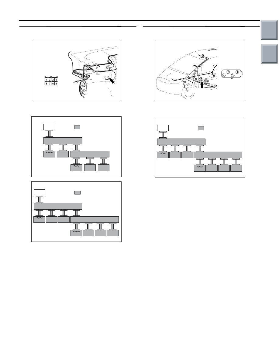
(1) Disconnect the EPS-ECU connector, and 

diagnose by using the M.U.T.-III.

AC206268AJ

<Vehicles without ASC>

METER/AC

ETACS

M.U.T.

J/C(1)

J/C(2)

ABS

EPS

ENG/CVT

: Red section on screen

AC206268AK

<Vehicles with ASC>

METER/AC

ETACS

SAS

M.U.T.

J/C(1)

J/C(2)

ASC

EPS

YR/G

ENG/CVT

: Red section on screen

(2) Check that the M.U.T.-III indications correspond 

to the illustration.

Q: Is the check result normal?

YES : 

<M.U.T.-III indications correspond to the 

illustration> Repair the wiring harness 
between joint connector (CAN2) and 
EPS-ECU connector.

NO : 

<M.U.T.-III indications do not correspond to 
the illustration> Check the EPS-ECU 
connector, and repair if necessary. If the 
EPS-ECU connector is in good condition, 
power supply to the EPS-ECU may be 
suspected. Diagnose the EPS system. 
Refer to GROUP 37 

− Troubleshooting 

P.37-74

.

STEP 9. M.U.T.-III CAN bus diagnostics (C-43 G 
and yaw rate sensor connector disconnected) 

AC601064

AB

C-43 (B)

Connector: C-43

Harness side

(1) Disconnect the G and yaw rate sensor connector, 

and diagnose by using the M.U.T.-III.

AC206268AK

<Vehicles with ASC>

METER/AC

ETACS

SAS

M.U.T.

J/C(1)

J/C(2)

ASC

EPS

YR/G

ENG/CVT

: Red section on screen

(2) Check that the M.U.T.-III indications correspond 

to the illustration.

Q: Is the check result normal?

YES : 

<M.U.T.-III indications correspond to the 

illustration> Repair the wiring harness 
between joint connector (CAN2) and G and 
yaw rate sensor connector.

NO : 

<M.U.T.-III indications do not correspond to 
the illustration> Check the G and yaw rate 
sensor connector, and repair if necessary. If 
the G and yaw rate sensor connector is in 
good condition, power supply to the G and 
yaw rate sensor may be suspected. 
Diagnose the ASC system. Refer to 
GROUP 35C 

− Troubleshooting 

P.35C-105

.

Main

Index

Group

TOC

TROUBLESHOOTING

CONTROLLER AREA NETWORK (CAN)

54D-34

STEP 10. M.U.T.-III CAN bus diagnostics (B-15 
combination meter connector disconnected)

AC401055

AE

Connector: B-15

B-15 (B)

Harness side

(1) Disconnect the combination meter connector, 

and diagnose by using the M.U.T.-III.

AC206268AJ

<Vehicles without ASC>

METER/AC

ETACS

M.U.T.

J/C(1)

J/C(2)

ABS

EPS

ENG/CVT

: Red section on screen

AC206268AK

<Vehicles with ASC>

METER/AC

ETACS

SAS

M.U.T.

J/C(1)

J/C(2)

ASC

EPS

YR/G

ENG/CVT

: Red section on screen

(2) Check that the M.U.T.-III indications correspond 

to the illustration.

Q: Is the check result normal?

YES : . 

<M.U.T.-III indications correspond to the 

illustration> Go to Step 12.

NO : . 

<M.U.T.-III indications do not correspond to 

the illustration> Go to Step 11.

STEP 11. M.U.T.-III CAN bus diagnostics (retest 
the system) 
Diagnose CAN bus lines, and check if M.U.T.-III 
screen shows normal state.

Q: Is the check result normal?

YES : 

<M.U.T.-III screen shows normal state> The 

trouble can be an intermittent malfunction 
(Refer to GROUP 00 

− How to use 

Troubleshooting/inspection Service Points 

− 

How to Cope with Intermittent Malfunction 

P.00-13

).

NO : 

<M.U.T.-III screen does not show normal 
state> Check the combination meter 
connector, and repair if necessary. If the 
combination meter connector is in good 
condition, refer to GROUP 54A 

− 

Combination meter 

− Troubleshooting 

P.54A-44

.

Main

Index

Group

TOC

TROUBLESHOOTING

CONTROLLER AREA NETWORK (CAN)

54D-35

STEP 12. M.U.T.-III CAN bus diagnostics [A-08 
engine-ECU <M/T> or engine-CVT-ECU <CVT> 
connector disconnected]

AC509191

Connector: A-08

Harness side

AD

A-08 (GR)

(1) Disconnect the engine-ECU <M/T> or 

engine-CVT-ECU <CVT> connector, and 
diagnose by using the M.U.T.-III.

AC206268AJ

<Vehicles without ASC>

METER/AC

ETACS

M.U.T.

J/C(1)

J/C(2)

ABS

EPS

ENG/CVT

: Red section on screen

AC206268AK

<Vehicles with ASC>

METER/AC

ETACS

SAS

M.U.T.

J/C(1)

J/C(2)

ASC

EPS

YR/G

ENG/CVT

: Red section on screen

(2) Check that the M.U.T.-III indications correspond 

to the illustration.

Q: Is the check result normal?

YES : . 

<M.U.T.-III indications correspond to the 

illustration>The trouble can be an 
intermittent malfunction (Refer to GROUP 
00 

− How to use Troubleshooting/inspection 

Service Points 

− How to Cope with 

Intermittent Malfunction 

P.00-13

).

NO : . 

<M.U.T.-III indications do not correspond to 

the illustration> Go to Step 13.

STEP 13. M.U.T.-III CAN bus diagnostics (retest 
the system) 
Diagnose CAN bus lines, and check if M.U.T.-III 
screen shows normal state.

Q: Is the check result normal?

YES : 

<M.U.T.-III screen shows normal state> The 

trouble can be an intermittent malfunction 
(Refer to GROUP 00 

− How to use 

Troubleshooting/inspection Service Points 

− 

How to Cope with Intermittent Malfunction 

P.00-13

).

NO : 

<M.U.T.-III screen does not show normal 
state> Check the engine-ECU <M/T> or 
engine-CVT-ECU <CVT>, and repair if 
necessary. If the engine-ECU <M/T> or 
engine-CVT-ECU <CVT> is in good 
condition, refer to GROUP 13A 

− 

Troubleshooting 

P.13A-281

 <N/A> or 

GROUP 13B 

− Troubleshooting 

P.13B-282


<T/C>.

Main

Index

Group

TOC

TROUBLESHOOTING

CONTROLLER AREA NETWORK (CAN)

54D-36

Diagnostic Item 2: Diagnose the CAN bus lines for short to earth.

CAUTION

When servicing a CAN bus line, earth yourself by touching a metal object such as an unpainted water 
pipe. If you fail to do, a component connected to the CAN bus line may be broken.

ETACS-ECU

STEERING WHEEL
SENSOR

COMBINATION
METER

DIAGNOSIS CONNECTOR

EPS-ECU

ABS-ECU

G AND YAW
RATE
SENSOR

ENGINE-ECU <M/T> OR
ENGINE-CVT-ECU <CVT>

NOTE

: VEHICLES WITHOUT ASC
: VEHICLES WITH ASC

Wire colour code
B : Black     LG : Light green     G : Green     L : Blue     W : White     Y : Yellow     SB : Sky blue
BR : Brown     O : Orange     GR : Grey     R : Red     P : Pink     V : Violet     PU : Purple

Main

Index

Group

TOC


Content   ..  299  300  301  302   ..