Mitsubishi Colt Ralliart. Manual - part 267
CAMSHAFT
ENGINE OVERHAUL <4A9>
11B-32
INSPECTION
M1113027000091
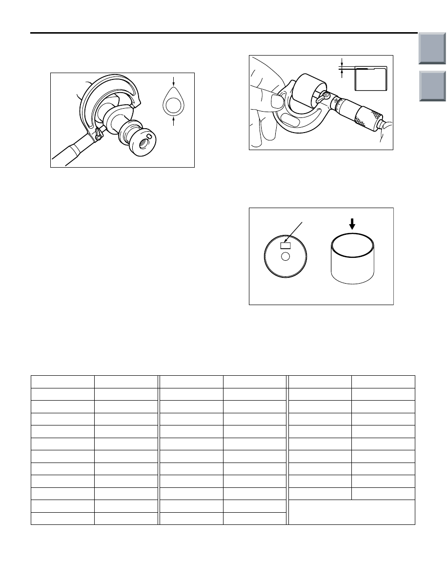
CAMSHAFT
AK304883
Measure the cam height. If the measured value
exceeds the limit, replace the camshaft.
Standard value:
Intake: 44.71 mm
Exhaust: 44.28 mm
Limit:
Intake: 44.21 mm
Exhaust: 43.78 mm
VALVE TAPPET
AK304938
AB
Wall
thickness
1. Measure the valve tappet at the illustrated
location. If the measured valve is discord to
instruction valve by identification mark and
following table, replace the tappet.
AK305693
Identification mark
AB
2. Every valve tappet has an identification mark
stamped at the illustrated location.
Valve tappets are available in 31 sizes, at 0.02
mm intervals in the 2.70
− 3.30 mm range, as
shown in the following table.
Thickness mm ID mark
Thickness mm ID mark
Thickness mm ID mark
2.70
70
2.92
92
3.14
14
2.72
72
2.94
94
3.16
16
2.74
74
2.96
96
3.18
18
2.76
76
2.98
98
3.20
20
2.78
78
3.00
00
3.22
22
2.80
80
3.02
02
3.24
24
2.82
82
3.04
04
3.26
26
2.84
84
3.06
06
3.28
28
2.86
86
3.08
08
3.30
30
2.88
88
3.10
10
2.90
90
3.12
12
Main
Index
Group
TOC