Mitsubishi Colt Ralliart. Manual - part 266
TIMING CHAIN
ENGINE OVERHAUL <4A9>
11B-28
NOTE: Valve tappets are available in 31 sizes, at
0.02 mm intervals in the 2.70
−
3.30 mm range.
AK304938
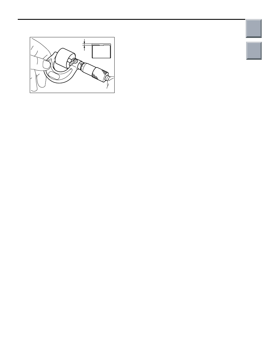
AB
Wall
thickness
9. Valve tappets should be selected in the following
manner.
(1) Remove the valve tappet and measure its
thickness.
(2) Calculate the correct thickness for a new valve
tappet as follows that achieves the standard
valve clearance.
A: Thickness of new valve tappet
B: Thickness of old valve tappet
C: Measured valve clearance
Equation:
Intake valve A = B + (C
− 0.22 mm)
Exhaust valve A = B + (C
− 0.30 mm)
For removal and installation procedures for the valve
tappet, refer to "CAMSHAFT REMOVAL AND
INSTALLATION."
(Refer to Camshaft Removal and Installa-
tion.
Main
Index
Group
TOC