Mitsubishi Colt Ralliart. Manual - part 265


  Index      Mitsubishi     Mitsubishi Colt Ralliart - service repair manual


Search            


Content   ..  263  264  265  266   ..


Mitsubishi Colt Ralliart. Manual - part 265


TIMING CHAIN

ENGINE OVERHAUL <4A9>

11B-24

TIMING CHAIN

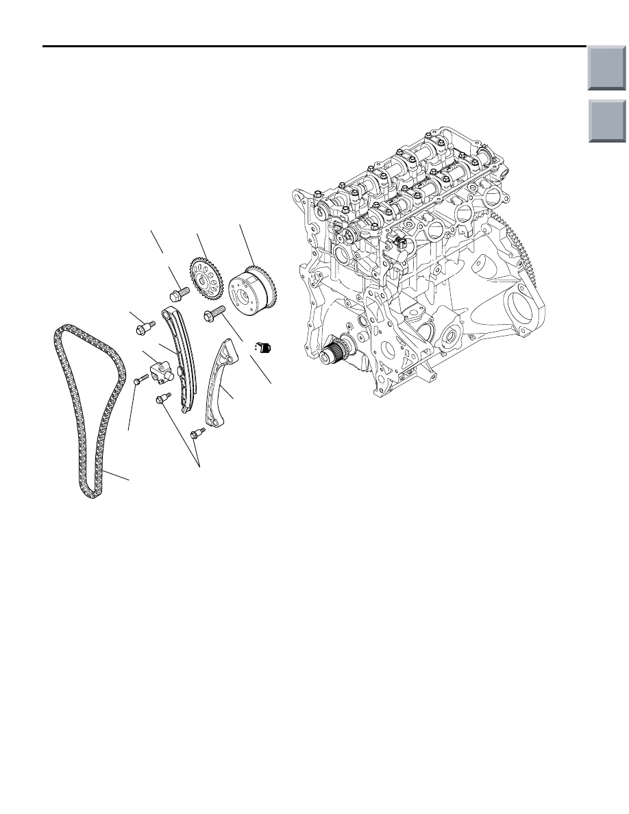
REMOVAL AND INSTALLATION

M1113026600216

AK402345

AE

64.9 ± 5.9 N·m

1

4

3

2

7

5

6

8

88 ± 10 N·m

23.5 ± 4.5 N·m

10 ± 2 N·m

8.4 ± 0.6 N·m

Removal steps 

>>

D

<< 1. Timing chain tensioner assembly

2. Tensioner lever assembly
3. Chain guide assembly

>>

C

<< 4. Timing chain

<<

A

>> >>

B

<< 5. Camshaft sprocket bolt

6. Camshaft sprocket

<<

B

>> >>

A

<< 7. V.V.T. sprocket bolt

8. V.V.T. sprocket assembly

Removal steps (Continued)

Main

Index

Group

TOC

TIMING CHAIN

ENGINE OVERHAUL <4A9>

11B-25

REMOVAL SERVICE POINTS
<<A>> CAMSHAFT SPROCKET BOLT 
REMOVAL

AK304922

While holding the hexagonal portion of the camshaft 
with a wrench, remove the camshaft sprocket bolt.

<<B>> V.V.T. SPROCKET BOLT REMOVAL

AK304923

While holding the hexagonal portion of the camshaft 
with a wrench, remove the V.V.T. sprocket bolt.

INSTALLATION SERVICE POINTS
>>A<< V.V.T. SPROCKET BOLT INSTAL-
LATION

AK305402AB

V.V.T.sprocket

V.V.T.sprocket
bolt

Camshaft

1. Apply a proper minimum quantity of engine oil to 

the following points.

• Camshaft end

• Insertion hole in V.V.T. sprocket (all over inside 

and outside surfaces)

• Threads and head of V.V.T. sprocket bolt

• Bearing surface of V.V.T. sprocket bolt

2. Install the V.V.T. sprocket onto the camshaft.
3. Make sure that the V.V.T. sprocket is installed all 

the way onto the camshaft. Holding the hexagonal 
portion of the camshaft with a wrench, check that 
the V.V.T. sprocket does not turn. 

AK304925

4. While holding the hexagonal portion of the 

camshaft with a wrench, tighten the V.V.T. 
sprocket bolt to 64.9 

± 5.9 N⋅m.

>>B<< CAMSHAFT SPROCKET BOLT 
INSTALLATION

AK304924

While holding the hexagonal portion of the camshaft 
with a wrench, tighten the sprocket bolt to 88 

± 10 

N

⋅m.

Main

Index

Group

TOC

TIMING CHAIN

ENGINE OVERHAUL <4A9>

11B-26

>>C<< TIMING CHAIN INSTALLATION

AK305394AB

V.V.T. 
sprocket
timing mark

Camshaft
sprocket
timing
mark

Timing chain
mark link 
plate (blue)

Timing chain mark
link plate (blue)

Crankshaft 
sprocket
timing mark

Timing mark

Timing mark

1. Place the timing chain such that the blue link that 

is away from the other two blue links of the chain 
is on the crankshaft side.

AK304930AB

Timing Mark

2. Install the timing chain onto the crankshaft 

sprocket, aligning the blue link with the mark on 
the sprocket.

AK304929AB

Timing mark

3. Install the chain onto the V.V.T. sprocket, aligning 

the blue link with the mark on the sprocket.

AK304926

AK304926

Timing mark

AB

4. Install the chain onto the camshaft sprocket, 

aligning the blue link with the mark on the 
sprocket. 
When doing this, rotate the V.V.T. sprocket or the 
camshaft sprocket by a tooth or two and then 
align the blue link and the mark.

5. Ensure that all of the 3 pairs of the timing marks 

are aligned.

6. Install the chain guide and the tensioner lever.

>>D<< TIMING CHAIN TENSIONER 
INSTALLATION

1. While pressing in the plunger of the timing chain 

tensioner, insert the pin as illustrated to lock the 
plunger.

AK304935

2. Install the timing chain tensioner onto the cylinder 

block, timing chain Tensioner bolts to 8.4 

± 0.6 

N

⋅m.

AK304877

3. Remove the pin from the tensioner. Timing chain 

should be tensioned via the tensioner lever.

Main

Index

Group

TOC

TIMING CHAIN

ENGINE OVERHAUL <4A9>

11B-27

INSPECTION

M1113026700075

VALVE CLEARANCE MEASUREMENT

Measure the valve clearance as illustrated.

AC312116

AB

MB992000

Crankshaft pulley
bolt and washer

Crankshaft

Dowel pin

Groove

Set the special tool Crankshaft adapter (MB992000) 
to the crankshaft, and install the crankshaft pulley 
bolt and washer.

AK305645AB

Timing mark

CAUTION

The crankshaft should always be rotated clock-
wise.
1. Rotate the crankshaft clockwise until the mark on 

the camshaft sprocket is aligned with the mark on 
the upper surface of cylinder head. (Set the No. 1 
cylinder to TDC on the compression stroke.)

AK305403AB

Timing chain side

Exhaust

Intake

2. Now, the valve clearance (shown with an arrow) 

can be measured.

AK304936

3. Using a thickness gauge, measure the clearance 

between the cam base circle and the valve tappet.

Standard value (cold engine):

Intake valve 0.22 

± 0.04 mm

Exhaust valve 0.30 

± 0.04 mm

4. If the measured value does not conform to the 

standard value, record the measured value.

AK305648AB

Timing mark

180˚

5. Rotate the crankshaft clockwise until the mating 

mark on the camshaft sprocket comes to the 
illustrated location. This will bring the No. 4 
cylinder to TDC on the compression stroke.

AK305403AC

Timing chain side

Exhaust

Intake

6. Measure the valve clearance at the location 

shown with an arrow.

7. If the measured value does not conform to the 

standard value, record the measured value.

8. Replace the valve tappet for the valve whose 

clearance is out of the standard value.

Main

Index

Group

TOC


Content   ..  263  264  265  266   ..