Mitsubishi Colt Ralliart. Manual - part 254
DRIVESHAFT ASSEMBLY
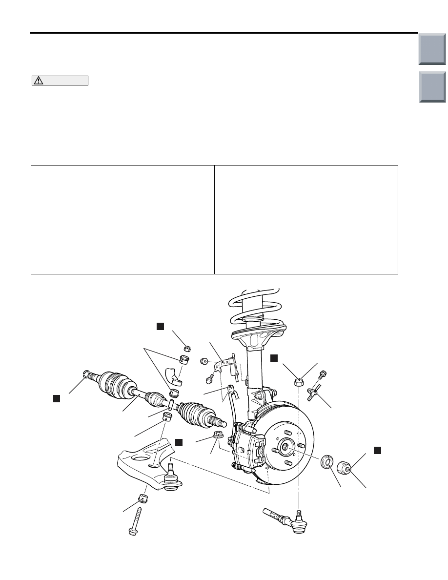
FRONT AXLE
26-16
DRIVESHAFT ASSEMBLY
REMOVAL AND INSTALLATION
M1261003501046
CAUTION
• The magnetic encoder collects any metallic particle easily, because it is magnetized. Make sure
that the magnetic encoder should not collect any metallic particle. Check that there is not any
trouble prior to reassembling it.
• When the driveshaft assembly is removed and installed, make sure that the magnetic encoder
does not contact with surrounding parts to avoid damage.
•
Pre-installation Operation
• Transmission Fluid Draining (Refer to GROUP
22, On-vehicle Service
− Transmission Oil
Replacement .), (Refer to GROUP 23,
On-vehicle Service
− Transmission Fluid (ATF)
.)
• Front Exhaust Pipe Removal (Refer to GROUP
15
− Exhaust Pipe and Main Muffler
,
.)
Post-installation Operation
• Front Exhaust Pipe Installation (Refer to
GROUP 15
− Exhaust Pipe and Main Muffler
).
• Check the Ball Joint Dust Cover for cracks or
damage by pushing it with your finger.
• Transmission Fluid Filling (Refer to GROUP 22,
On-vehicle Service
− Transmission Oil
Replacement .), (Refer to GROUP 23,
On-vehicle Service
− Transmission Fluid (ATF)
Replacement
).
AC207334 AE
N
1
2
245 ± 29 N·m
3
4
6
N
7
7
7
8
N
9
25 ± 5 N·m
10
N
66 ± 6 N·m
11
12
N
5
<4A9>
When the front wheel speed sensor is removed and installed, make sure that its pole piece does
not contact with surrounding parts to avoid damage.
Main
Index
Group
TOC