Mitsubishi Colt Ralliart. Manual - part 246


  Index      Mitsubishi     Mitsubishi Colt Ralliart - service repair manual


Search            


Content   ..  244  245  246  247   ..


Mitsubishi Colt Ralliart. Manual - part 246


ON-VEHICLE SERVICE

ANTI-SKID BRAKING SYSTEM (ABS)

35B-76

ON-VEHICLE SERVICE

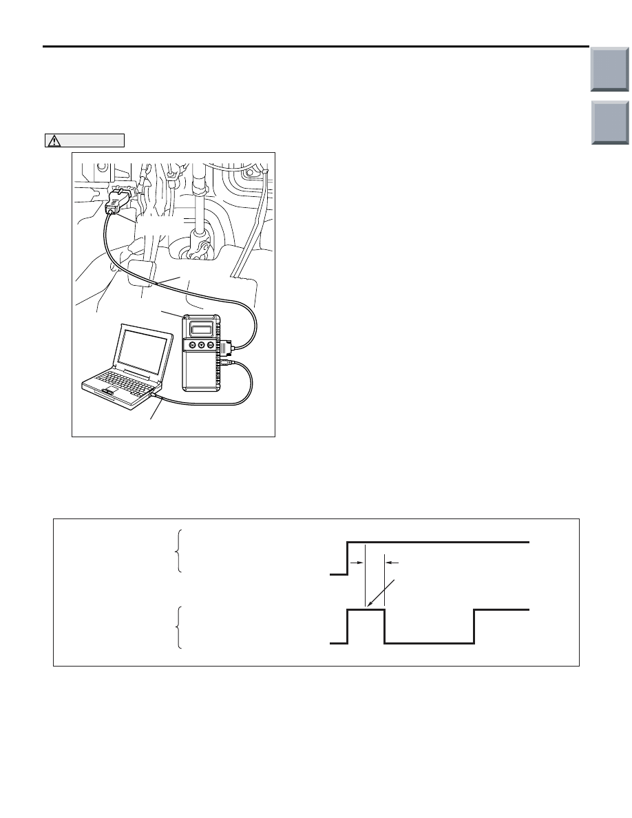
HYDRAULIC UNIT CHECK

M1352001700705

1. Raise the vehicle, and support the specified area 

on axle stands.

CAUTION

Before connecting or disconnecting the 
M.U.T.-III, turn the ignition switch to the "LOCK" 
(OFF) position.
2. Turn the ignition switch to the "LOCK (OFF)" 

position, and then set the M.U.T.-III.

3. Check that the selector lever is "N" position, and 

then start the vehicle engine.

4. Operate the M.U.T.-III to execute the actuator test 

while depressing the brake pedal. When 
executing the actuator test, check that the braking 
force changes by rotating the wheel with your 
hand.
NOTE: During the actuator test, the ABS warning 
lamp illuminates and ABS control is prohibited.
NOTE: When the ABS-ECU is not working due to 
the fail-safe, the M.U.T.-III actuator test cannot be 
executed.

5. This is indicated as shown above.

6. When it is abnormal as a result of the inspection, 

take action as described on the "Judgment table".

AC206895

AD

Diagnosis

connector

MB991827

MB991824 

MB991910

AC106011

M.U.T.-III actuator test
(No.01, 02, 03, 04) start

Approx. 3 seconds

Pedal operation

Drag force when pedal is free

Lock

Depress

Release

Brake force check

AD

Approx. 0.05 seconds

Main

Index

Group

TOC

ON-VEHICLE SERVICE

ANTI-SKID BRAKING SYSTEM (ABS)

35B-77

JUDGMENT TABLE

7. Turn the ignition switch to LOCK (OFF) position, 

and then remove the M.U.T.-III after the 
inspection. 

IN THE EVENT OF A DISCHARGED 
BATTERY

M1352003500633

WARNING

If the ABS is not operating, the vehicle pos-
ture will be unstable during braking, Do not 
drive the vehicle with the ABS-ECU connec-
tor disconnected or with the ABS not operat-
ing for any other reason.

If the engine is started using a booster cable when 
the battery is completely flat, and the vehicle is then 
driven without waiting for the battery to be recharged, 
the engine may misfire and it may not be possible to 
drive the vehicle. This is because the ABS consumes 
a large amount of current when carrying out its initial 
checks. If this happens, recharge the battery fully.

Display on 
M.U.T.-III

Operation

Inspection 
results

Judgment Cause

Action

01 FR wheel 
ABS
02 FL wheel 
ABS
03 RR wheel 
ABS
04 RL wheel 
ABS

• Depress the brake 

pedal and lock the 
wheels.

• Select a wheel 

which is inspected 
on the M.U.T.-III 
and execute the 
actuator test.

• Rotate the wheel 

selected and 
check the braking 
force.

The braking 
force has been 
weakened for 3 
seconds in the 
locked states.

Normal

The wheel is 
not locked 
when 
depressing the 
brake pedal.

Trouble

Clogged brake line 
other than hydraulic 
unit

The inspection 
and cleaning of 
brake line

Clogged hydraulic 
pressure circuit inside 
of hydraulic unit

Replace the 
hydraulic unit 
assembly

The braking 
force has not 
been 
weakened

The improper lines of 
hydraulic unit brake 
tube

Correct the 
lines.

Malfunction of 
hydraulic unit solenoid 
valve operation

Replace the 
hydraulic unit 
assembly

Main

Index

Group

TOC

HYDRAULIC UNIT

ANTI-SKID BRAKING SYSTEM (ABS)

35B-78

HYDRAULIC UNIT

REMOVAL AND INSTALLATION

M1352018400104

Pre-removal operation
• Brake Fluid Draining

• Air cleaner body assembly removal (Refer to GROUP 15, 

Air Cleaner 

P.15-5

).

• Fuel Vapour Canister Removal 

(Refer to GROUP 17, Canister 

P.17-18

).

Post-installation operation
• Fuel Vapour Canister Installation 

(Refer to GROUP 17, Canister 

P.17-18

).

• Air cleaner body assembly installation (Refer to GROUP 

15, Air Cleaner 

P.15-5

).

• Brake Line Bleeding (Refer to GROUP 35A, On-vehicle 

Service 

P.35A-10

).

• Hydraulic Unit Check (Refer to 

P.35B-76

).

AC208927

AC208498

AB

15 ± 2 N·m

2

2

4

1

5

6

3

7

8 ± 2 N·m

2

N

18 ± 3 N·m

N

18 ± 3 N·m

Removal steps 

<<

A

>>

1.

ABS-ECU harness connector

>>

A

<<

2.

Brake tube connection

3.

Fuel vapour canister bracket

4.

Connection of brake tube and clip

<<

B

>>

5.

Hydraulic unit (ABS-ECU)

6.

Hydraulic unit bracket insulator

7.

Hydraulic unit bracket

Removal steps (Continued)

Main

Index

Group

TOC

HYDRAULIC UNIT

ANTI-SKID BRAKING SYSTEM (ABS)

35B-79

REMOVAL SERVICE POINTS
<<A>> HARNESS CONNECTOR DISCON-
NECTION

Move the lock lever of the ABS-ECU connector as 
shown in the illustration, and then disconnect the 
harness connector.

<<B>> HYDRAULIC UNIT (ABS-ECU) 
REMOVAL

WARNING

The hydraulic unit is heavy. Use care when 
removing it.

CAUTION

• The hydraulic unit cannot be disassembled. 

Never loosen its nuts or bolts.

• Do not drop or shock the hydraulic unit.
• Do not turn the hydraulic unit upside down or 

lay it on its side.

INSTALLATION SERVICE POINTS
>>A<< BRAKE TUBE INSTALLATION

Install each brake tube according to the colour of the 
flare nut as shown.

AC208370AB

Lock lever

AC208649AB

Green

Yellow

Main

Index

Group

TOC


Content   ..  244  245  246  247   ..