Mitsubishi Colt Ralliart. Manual - part 244


  Index      Mitsubishi     Mitsubishi Colt Ralliart - service repair manual


Search            


Content   ..  242  243  244  245   ..


Mitsubishi Colt Ralliart. Manual - part 244


TROUBLESHOOTING

ANTI-SKID BRAKING SYSTEM (ABS)

35B-68

COMMENTS ON TROUBLE SYMPTOM

• If the ABS system fails, the ABS-ECU will send a 

lamp drive signal to the combination meter 
through the CAN communication lines.

• If the combination meter detects a ABS time-out 

due to a failure in the power supply to the 
ABS-ECU or abnormal CAN communication, the 
combination meter illuminates the lamp.

• If the CAN bus communication fails, refer to 

GROUP 54D, CAN Bus Diagnostics Table 

P.54D-13

.

• If a trouble occurs in the power supply to the 

ABS-ECU (i.e. excessively high resistance in the 
power supply or earth lines), this trouble symp-
tom will appear., but the diagnosis code will not 
be set. Then, if you drive the vehicle at 6 km/h or 
more, the ECU will set diagnosis code C1861.

• Perform the actuator test to extinguish the lamp 

in the combination meter. If it does not extinguish, 
replace the combination meter. If it extinguishes, 
replace the ABS-ECU.

• It is also suspected that the combination meter 

does not obey the commands from the 
ABS-ECU. If the combination meter does not 
function after the ABS-ECU is replaced, replace 
the combination meter.

POSSIBLE CAUSES

• Damaged harness wires and connectors

• Defective combination meter (incorporating the 

meter-ECU)

• The ABS-ECU is defective.

• The power supply circuit is defective.

DIAGNOSIS PROCEDURE

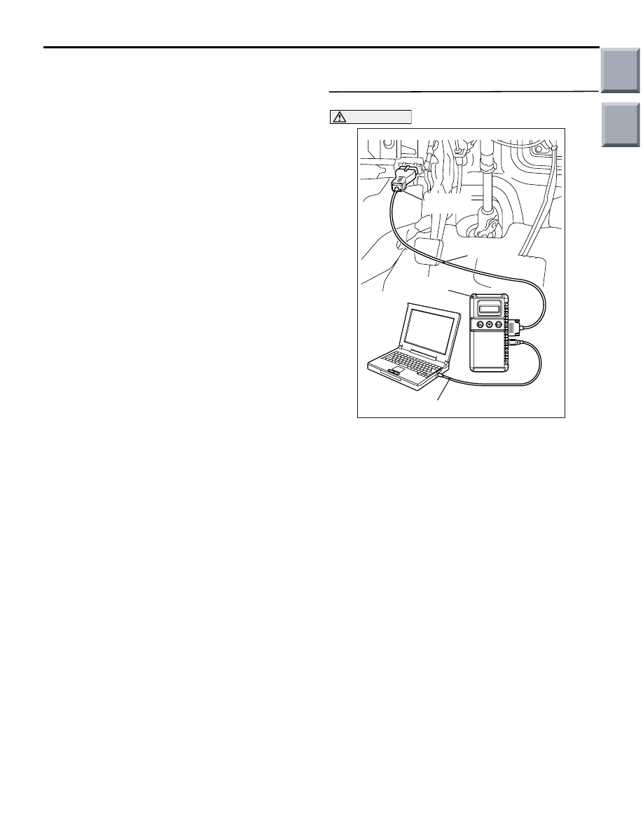
STEP 1. M.U.T.-III CAN bus diagnostics

CAUTION

Before connecting or disconnecting the 
M.U.T.-III, turn the ignition switch to the "LOCK" 
(OFF) position.
(1) Connect M.U.T.-III to the 16-pin diagnosis 

connector.

(2) Turn the ignition switch to the "ON" position.
(3) Diagnose the CAN bus line.
(4) Turn the ignition switch to the "LOCK" (OFF) 

position.

Q: Is the check result normal?

YES : 

Go to Step 2.

NO : 

Repair the CAN bus line (Refer to GROUP 
54D, Diagnosis 

P.54D-13

).

AC206895

AC

Diagnosis

connector

MB991827

MB991824 

MB991910

Main

Index

Group

TOC

TROUBLESHOOTING

ANTI-SKID BRAKING SYSTEM (ABS)

35B-69

STEP 2. M.U.T.-III diagnosis code

CAUTION

Before connecting or disconnecting the 
M.U.T.-III, turn the ignition switch to the "LOCK" 
(OFF) position.
(1) Connect M.U.T.-III to the 16-pin diagnosis 

connector.

(2) Turn the ignition switch to the "ON" position.
(3) Check whether the ABS-related diagnosis code is 

set.

(4) Turn the ignition switch to the "LOCK" (OFF) 

position.

Q: Is the check result normal?

YES : 

Go to Step 3.

NO : 

Carry out the diagnosis for the diagnosis 
code (Refer to 

P.35B-7

).

STEP 3. M.U.T.-III diagnosis code

CAUTION

Before connecting or disconnecting the 
M.U.T.-III, turn the ignition switch to the "LOCK" 
(OFF) position.
(1) Connect M.U.T.-III to the 16-pin diagnosis 

connector.

(2) Turn the ignition switch to the "ON" position.
(3) Drive the vehicle at 10 km/h or more. Then use 

the M.U.T.-III to check whether the ABS 
diagnosis code is reset.

(4) Turn the ignition switch to the "LOCK" (OFF) 

position.

Q: Is the check result normal?

YES : 

Go to Step 4.

NO : 

Carry out the diagnosis for the diagnosis 
code (Refer to 

P.35B-7

).

AC206895

AC

Diagnosis

connector

MB991827

MB991824 

MB991910

AC206895

AC

Diagnosis

connector

MB991827

MB991824 

MB991910

Main

Index

Group

TOC

TROUBLESHOOTING

ANTI-SKID BRAKING SYSTEM (ABS)

35B-70

STEP 4. M.U.T.-III actuator test

CAUTION

Before connecting or disconnecting the 
M.U.T.-III, turn the ignition switch to the "LOCK" 
(OFF) position.
(1) Connect M.U.T.-III to the 16-pin diagnosis 

connector.

(2) Turn the ignition switch to the "ON" position.
(3) Execute combination meter actuator test.

• Item A1: Indicator lamp and warning lamp 

(extinguish)

(4) Turn the ignition switch to the "LOCK" (OFF) 

position.

(5) Disconnect M.U.T.-III.

Q: Does the ABS warning lamp extinguish normally?

YES : . 

Replace the combination meter (integrated 

with meter-ECU) (Refer to GROUP 54A, 
Combination Meter 

P.54A-67

). Then go to 

Step 5.

NO : . 

Replace the hydraulic unit (integrated with 

ABS-ECU) (Refer to 

P.35B-78

).

STEP 5. Recheck the trouble symptom.

Q: Does the ABS warning lamp extinguish after the 

engine has been started?
YES : 

This diagnosis is complete.

NO : 

Replace the combination meter (integrated 
with meter-ECU) (Refer to GROUP 54A, 
Combination Meter 

P.54A-67

).

AC206895

AC

Diagnosis

connector

MB991827

MB991824 

MB991910

Main

Index

Group

TOC

TROUBLESHOOTING

ANTI-SKID BRAKING SYSTEM (ABS)

35B-71

Inspection Procedure 5: The ABS operates too frequently (no diagnosis code is set)

COMMENTS ON TROUBLE SYMPTOM

• This trouble symptom will not appear due to a 

failure in wiring harness (open or short circuit, or 
excessive resistance). Therefore, if the sensors 
are installed properly and the check result does 
not indicate any problems, replace the ABS-ECU.

POSSIBLE CAUSES

• Wheel speed sensor malfunction

• Hub malfunction

• ABS-ECU malfunction

DIAGNOSIS PROCEDURE

STEP 1. Check the wheel speed sensors for 
proper installation.
Check that the wheel speed sensors are installed 
correctly (e.g. loosely tightened bolts).

Q: Is the check result normal?

YES : 

Go to Step 2.

NO : 

Reinstall the wheel speed sensor(s) 
properly.

STEP 2. Remove the wheel speed sensors and 
check them.
Refer to 

P.35B-81

.

Q: Is the check result normal?

YES : 

Go to Step 3.

NO : 

Replace the wheel speed sensor (Refer to 

P.35B-80

).

STEP 3. Check the encoder for detecting wheel 
speed.
Check the encoder for presence of foreign objects or 
deformation.

Q: Is the check result normal?

YES : 

Go to Step 4.

NO : 

If foreign objects are found, clean the 
encoder. If deformation is found, replace the 
hub [Refer to GROUP 26, Front Axle Hub 
Assembly 

P.26-6

 <Front (vehicles with 14 

inch brake)> or 

P.26-9

 <Front (vehicles with 

15 inch brake)> or GROUP 27, Rear Axle 
Hub 

P.27-6

 <Rear>].

STEP 4. Check the wheel bearing for excessive 
play.
Front: refer to GROUP 26, On-vehicle Service 

− 

Wheel Bearing Axial Play Check 

P.26-5

.

Rear: refer to GROUP 27, On-vehicle Service 

− 

Wheel Bearing Axial Play Check 

P.27-3

.

Q: Is the check result normal?

YES : 

Go to Step 5.

NO : 

Replace the hub assembly [Refer to 
GROUP 26, Front Axle Hub Assembly 

P.26-6

 <Front (vehicles with 14 inch brake)> 

or 

P.26-9

 <Front (vehicles with 15 inch 

brake)> or GROUP 27, Rear Axle Hub 

P.27-6

 <Rear>].

STEP 5. Recheck the trouble symptom.

Q: Does the ABS operate too frequently?

YES : 

The malfunction is intermittent. Refer to 

GROUP 00, How to Use 
Troubleshooting/Inspection Service Points 

− 

How to Cope with Intermittent Malfunction 

P.00-13

.

NO : 

Replace the hydraulic unit (integrated with 
ABS-ECU) (Refer to 

P.35B-78

).

Main

Index

Group

TOC


Content   ..  242  243  244  245   ..