Mitsubishi Colt Ralliart. Manual - part 242


  Index      Mitsubishi     Mitsubishi Colt Ralliart - service repair manual


Search            


Content   ..  240  241  242  243   ..


Mitsubishi Colt Ralliart. Manual - part 242


TROUBLESHOOTING

ANTI-SKID BRAKING SYSTEM (ABS)

35B-60

Inspection Procedure 2: ABS-ECU power supply system
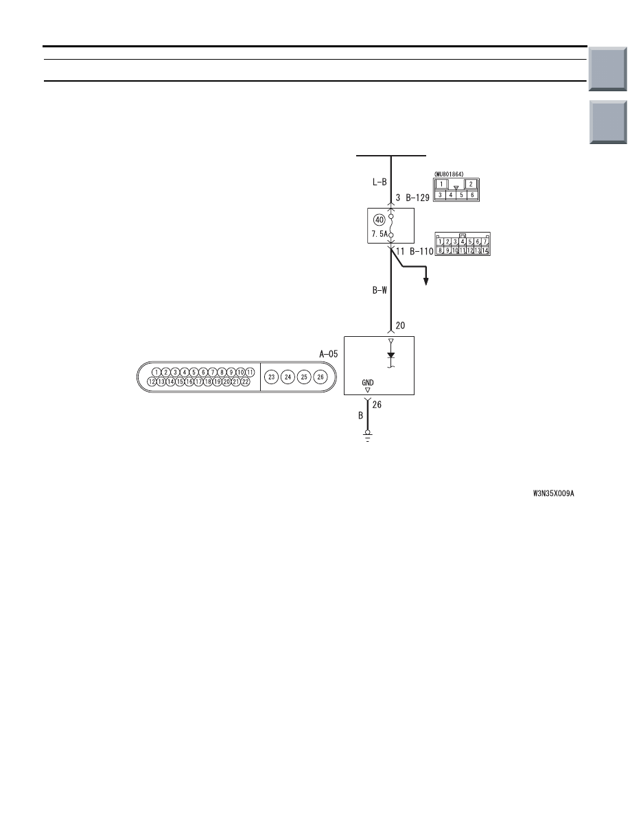
OPERATION

• The ABS-ECU is energized by the ignition switch 

(IG1) through multi-purpose fuse 2 and the 
ABS-ECU terminal 20.

• If the power supply to the ABS-ECU has failed, 

M.U.T.-III will not be able to communicate with it.

PROBABLE CAUSES

• Damaged wiring harness or connector

• Defective battery

• Charging system failed

• Malfunction of the hydraulic unit (integrated with 

ABS-ECU)

IGNITION
SWITCH (IG1)

ELECTRIC
POWER
STEERING
SYSTEM

ABS-ECU

Wire colour code
B : Black     LG : Light green     G : Green     L : Blue     W : White     Y : Yellow     SB : Sky blue
BR : Brown     O : Orange     GR : Gray     R : Red     P : Pink     V : Violet

ABS-ECU Power Supply and Earth Circuit

Main

Index

Group

TOC

TROUBLESHOOTING

ANTI-SKID BRAKING SYSTEM (ABS)

35B-61

DIAGNOSIS PROCEDURE

STEP 1. Voltage measurement at ABS-ECU 
connector A-05.

(1) Disconnect the connector A-05, and connect 

special tool ABS Check Harness (MB991974) to 
the wiring harness-side connector.
NOTE: . Do not connect special tool ABS Check 
Harness (MB991974) to the ABS-ECU.

(2) Turn the ignition switch to the "ON" position.

(3) Measure the voltage between terminal 20 and 

earth.

OK: System voltage

Q: Is the check result normal?

YES : 

Go to Step 3.

NO : 

Go to Step 2.

AC313863AB

Connector: A-05

Harness side

A-05(B)

AC314249AB

ABS-ECU

MB991951

Check connector

A-05 Harness connector

AC313972 AZ

Check connector
 (Harness side)

Main

Index

Group

TOC

TROUBLESHOOTING

ANTI-SKID BRAKING SYSTEM (ABS)

35B-62

STEP 2. Connector check: ABS-ECU connector 
A-05, ignition switch connector B-141, junction 
block connectors C-110 and C-129

Check the connectors, for loose, corroded or dam-
aged terminals, or terminals pushed back in the con-
nector.

Q: Is the check result normal?

YES : 

An open or short circuit may be present in 

the power supply line to the ABS-ECU. 
Repair the wiring harness between 
ABS-ECU connector A-05 terminal 20 and 
ignition switch connector B-141 terminal 2. 
Go to Step 8.

NO : 

Repair or replace the damaged 
component(s). Then go to Step 8.

AC313863AB

Connector: A-05

Harness side

A-05(B)

AC313874AC

Connector: B-141

Harness side

AC313870AI

Connector: B-110

Junction Block (Front view)

Junction block side

12

5

9

8

1 2

1011

3 4

14

13

6 7

AC313872AJ

Connector: B-129

Junction Block (Rear view)

Junction block side

Main

Index

Group

TOC

TROUBLESHOOTING

ANTI-SKID BRAKING SYSTEM (ABS)

35B-63

STEP 3. Resistance measurement at ABS-ECU 
connector A-05.

(1) Disconnect the connector A-05, and connect 

special tool ABS Check Harness (MB991974) to 
the wiring harness-side connector.
NOTE: Do not connect special tool ABS Check 
Harness (MB991974) to the ABS-ECU.

(2) Measure the resistance between terminal 26 and 

earth.

OK: Continuity exists (2 

 or less)

Q: Is the check result normal?

YES : 

Go to Step 5.

NO : 

Go to Step 4.

STEP 4. Check ABS-ECU connector A-05 for 
loose, corroded or damaged terminals, or 
terminals pushed back in the connector.

Q: Is the check result normal?

YES : 

An open circuit may be present in the earth 

circuit. Repair the wiring harness between 
ABS-ECU connector A-05 terminals 26 and 
the body earth. Then go to Step 8.

NO : 

Repair or replace the damaged 
component(s). Then go to Step 8.

STEP 5. Check the battery.
Check the battery (Refer to GROUP 54A, Battery 
test 

P.54A-5

).

Q: Is the check result normal?

YES : 

Go to Step 6.

NO : 

Charge or replace the battery. Then go to 
Step 8.

STEP 6. Check the charging system.
Check the charging system (Refer to GROUP 16, 
Charging system 

P.16-6

).

Q: Is the check result normal?

YES : 

Go to Step 7.

NO : 

Repair or replace the charging system 
component(s).Then go to Step 8.

AC313863AB

Connector: A-05

Harness side

A-05(B)

AC314249AB

ABS-ECU

MB991951

Check connector

A-05 Harness connector

AC313972BB

1

2

3

4

5

7

8

9

10

11

18

19

20

21

22

13

14

15

16

17

6

12

23

24

25

26

Check connector
 (Harness side)

AC313863AB

Connector: A-05

Harness side

A-05(B)

Main

Index

Group

TOC


Content   ..  240  241  242  243   ..