Mitsubishi Colt Ralliart. Manual - part 208


  Index      Mitsubishi     Mitsubishi Colt Ralliart - service repair manual


Search            


Content   ..  206  207  208  209   ..


Mitsubishi Colt Ralliart. Manual - part 208


STRUT ASSEMBLY

FRONT SUSPENSION

33-9

DISASSEMBLY SERVICE POINTS
<<A>> STRUT NUT (SELF-LOCKING NUT) 
REMOVAL

CAUTION

• Install special tool arm set (MB991238) evenly, 

and so that the maximum length will be 
attained within the installation range.

AC001085AB

MB991238

MB991237

Do not use an impact wrench to tighten the 
bolt of special tool spring compressor body 
(MB991237), otherwise the special tool will 
break.

1. Use following special tools to compress the coil 

spring.

• Spring compressor body (MB991237)

• Arm set (MB991238)

WARNING

Do not use an impact wrench to remove the 
strut nut (self-locking nut). Vibration of the 
impact wrench will cause special tools 
(MB991237 and MB991238) to slip and cause 
personal injury.

AC006091 AB

MB991681

MB991682

2. Use following special tools to secure the strut, and 

then remove the strut nut (self-locking nut).

• Wrench (MB991681)

• Socket (MB991682)

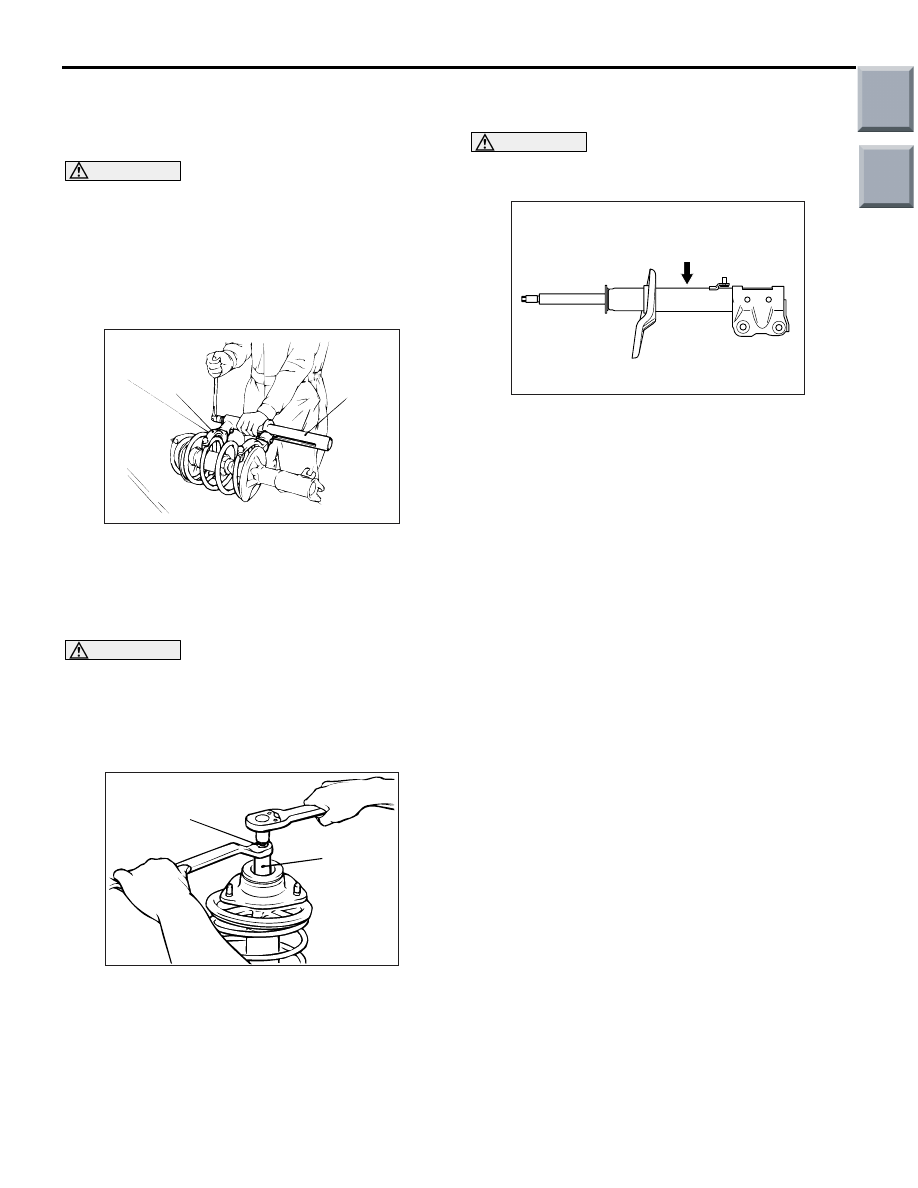
<<B>> STRUT DISPOSAL

WARNING

Wear goggles when drilling to protect your 
eyes from flying metal debris.

AC207801

AC

The gas must be discharged from the strut before 
discarding it. Place the strut horizontally with its pis-
ton rod extended. Then drill a hole of approximately 
3 mm in diameter at the location shown in the illustra-
tion and discharge the gas.

Main

Index

Group

TOC

STRUT ASSEMBLY

FRONT SUSPENSION

33-10

REASSEMBLY SERVICE POINTS
>>A<< STRUT NUT (SELF-LOCKING NUT) 
INSTALLATION

1. Ensure that the bearing is seated correctly.

CAUTION

Do not use an impact wrench to tighten the bolt 
of special tool spring compressor body 
(MB991237), otherwise the special tool will break.

AC001085AB

MB991238

MB991237

2. Install following special tools to the strut assembly 

same as its removal.

• Spring compressor body (MB991237)

• Arm set (MB991238)

3. While the coil spring is being compressed by the 

special tools, temporarily tighten the strut nut 
(self-locking nut).

4. Align the hole in the strut spring lower seat with 

the hole in the spring upper seat.
NOTE: 

AC006091 AB

Rod

Using a rod as shown facilitates the alignment.

5. Align lower end of the coil spring with the groove 

in the spring lower seat, and then loosen the 
special tools.

CAUTION

Do not use an impact wrench to tighten the 
self-locking nut, otherwise the strut nut 
(self-locking nut) will be damaged.

AC006091 AB

MB991681

MB991682

6. Using following special tools, tighten the strut nut 

(self-locking nut) to 60 

± 10 N⋅m.

• Wrench (MB991681)

• Socket (MB991682)

INSPECTION

M1332001400188

• Check the strut bearing for wear or rust.

• Check the rubber parts for damage or deteriora-

tion.

• Check the coil spring for deformation, deteriora-

tion or damage.

• Check the strut for deformation.

Main

Index

Group

TOC

LOWER ARM

FRONT SUSPENSION

33-11

LOWER ARM

REMOVAL AND INSTALLATION <4A9>

M1332001600911

CAUTION

*

: Indicates parts which should be temporarily tightened, and then fully tightened with the vehicle on 

the earth in an unladen condition.

Post-installation Operation
• Check the dust cover for cracks or damage by pushing it 

with finger.

• Front wheel alignment check and adjustment (Refer to 

P.33-5

).

AC314212

AC

AB

1

66 ± 6 N·m

2

3

4

3

5

123 ± 12 N·m

6

7

7

123 ± 12 N·m

Specified grease: Multipurpose grease 
SAE J310, NLGI No.2 or equivalent

Removal steps 

<<

A

>>

1.

Self-locking nut (Lower arm and 
knuckle connection)

>>

A

<< 2.

Self-locking nut

3.

Stabilizer rubber

4.

Collar

5.

Nut (Lower arm and crossmember 
connection)

6.

Bolt (Lower arm and crossmember 
connection)

7.

Lower arm assembly

Removal steps (Continued)

Main

Index

Group

TOC

LOWER ARM

FRONT SUSPENSION

33-12

REMOVAL SERVICE POINT
<<A>> SELF-LOCKING NUT REMOVAL 
(LOWER ARM BALL JOINT DISCONNEC-
TION)

CAUTION

• The self-locking nut must be only loosened 

but not removed from the ball joint. Be sure to 
use the special tool.

AC208247AL

Cord

Bolt

MB991897 or
MB992011

Self-locking
nut

Ball joint

To prevent the special tool from dropping off, 
suspend it with a cord.

1. Install the special tool ball joint remover 

(MB991897 or MB992011) as shown in the figure.

AC104739AB

Parallel

Knob

Bolt

Correct

Wrong

2. Turn the bolt and knob to make the special tool 

insert horizontal, then hand-tighten the bolt. After 
tightening, verify that the insert is still horizontal.
NOTE: . When adjusting the special tool wedge 
horizontally, position the knob as shown.

3. Turn the bolt to disengage the lower arm ball joint 

from the knuckle.

INSTALLATION SERVICE POINT
>>A<< SELF-LOCKING NUT INSTALLA-
TION

AC207017AB

A

Tighten the self-locking nut until its protruding length 
meets the standard value (A).

Standard value (A): 19 

± 1.5 mm

Main

Index

Group

TOC


Content   ..  206  207  208  209   ..