Mitsubishi Colt Ralliart. Manual - part 207


  Index      Mitsubishi     Mitsubishi Colt Ralliart - service repair manual


Search            


Content   ..  205  206  207  208   ..


Mitsubishi Colt Ralliart. Manual - part 207


MB990800

ON-VEHICLE SERVICE

FRONT SUSPENSION

33-5

ON-VEHICLE SERVICE

FRONT WHEEL ALIGNMENT CHECK AND 
ADJUSTMENT

M1331000901050

Measure wheel alignment with alignment equipment 
on a level surface. The front suspension, steering 
system, wheels, and tyres should be serviced to nor-
mal condition before measuring wheel alignment.
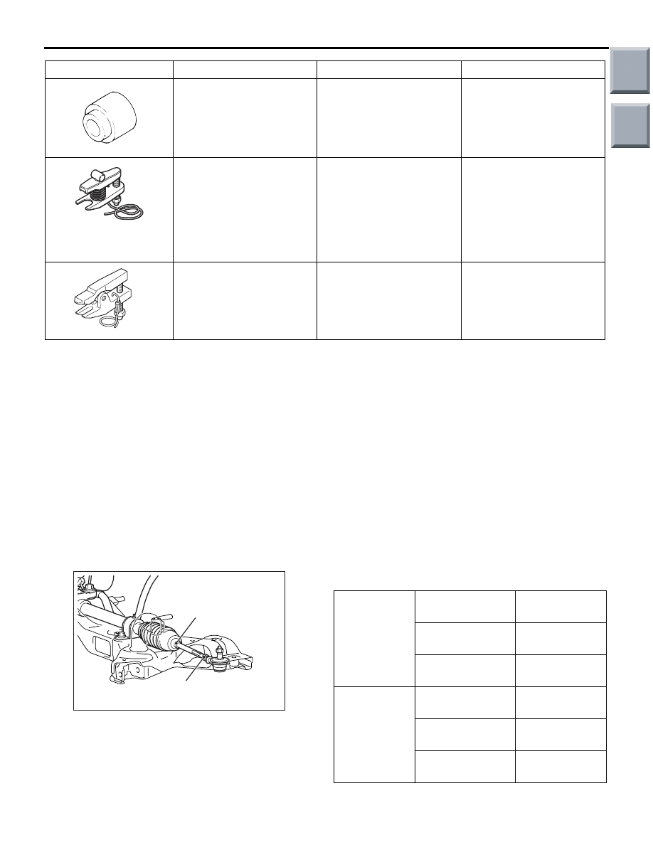
TOE-IN

Standard value:

At the centre of tyre tread: 0 

± 2 mm

Toe angle (per wheel): 0

°00' ± 0°06'

AC209087AE

Lock nut

Clip

1. Adjust the toe-in by undoing the clip and lock nut, 

and turning the left and right tie rod turnbuckles by 
the same amount (in opposite directions).

NOTE: The toe will move out as the left turnbuckle 
is turned toward the front of the vehicle and the 
right turnbuckle is turned toward the rear of the 
vehicle.

2. Install the clip and tighten the lock nut to the 

specified torque.

Tightening torque: 43 

± 7 Nm

3. Confirm that the toe-in is at the standard value.
4. Use a turning radius gauge to check that the 

steering angle is at the standard value.

STEERING ANGLE
Standard value:

Inner wheels

Vehicles with 
14-inch wheels

41

° 40' ± 1° 30'

Vehicles with 
15-inch wheels

39

° 00' ± 1° 30'

Vehicles with 
16-inch wheels

34

° 10' ± 1° 30'

Outer wheels 
(reference)

Vehicles with 
14-inch wheels

35

° 30'

Vehicles with 
15-inch wheels

33

° 40'

Vehicles with 
16-inch wheels

30

° 00'

MB990800

Ball joint remover and 
installer

Lower arm ball joint cover 
installation

MB991897

MB991897 or MB992011

Ball joint remover

Knuckle and ball joint 
disconnection <4A9>
NOTE: Steering linkage 
puller (MB990635 or 
MB991113)is also used to 
disconnect knuckle and tie 
rod end ball joint.

B991113    

MB991113

Steering linkage puller

Knuckle and ball joint 
disconnection <4G1>

Tool

Number

Name

Use

Main

Index

Group

TOC

ON-VEHICLE SERVICE

FRONT SUSPENSION

33-6

CAMBER, CASTER AND KINGPIN 
INCLINATION

Standard value:

Item

Specification

Camber

<4A9>

− 0°30' ± 0°30'*

<4G1>

− 0°30' ± 0°45'*

Caster

<4A9>

2

°35' ± 0°30'*

<4G1>

2

°40' ± 0°45'*

Kingpin inclination

13

°20' ± 0°30'

NOTE: *: Difference between right and left wheels 
must be less than 30'
NOTE: Camber and caster are preset at the factory 
and cannot be adjusted.

CAUTION

Never subject the wheel bearings to the vehicle 
load when the driveshaft nuts are loosened.
NOTE: 

AC208980AD

MB991004

245 ± 29 N·m

For vehicles with aluminium wheels, attach the cam-
ber/caster/kingpin gauge to the driveshaft by using 
special tool wheel alignment gauge attachment 
(MB991004). Tighten the special tool to the same 
torque 245 

±

 29 N

m as the driveshaft nut.

LOWER ARM BALL JOINT AXIAL PLAY 
CHECK

M1332011300074

1. Raise the vehicle.
2. Remove the stabilizer link from the lower arm.
3. Move the lower arm up and down with your hands 

to check for an excessive play in the axial 
direction of the ball joint. If there is an excessive 
play, replace the lower arm assembly.

LOWER ARM BALL JOINT COVER 
CHECK

M1332008600321

1. Press the lower arm ball joint cover with your 

finger to check that there are no cracks or 
damage in the lower arm ball joint cover.

2. If the lower arm ball joint cover is cracked or 

damaged, replace the lower arm assembly.
NOTE: If the lower arm ball joint cover is cracked 
or damaged, it is possible that there may also be 
damage to the ball joint.

Main

Index

Group

TOC

STRUT ASSEMBLY

FRONT SUSPENSION

33-7

STRUT ASSEMBLY

REMOVAL AND INSTALLATION

M1332001100488

Pre-removal Operation
Cowl top panel (Refer to GROUP 42, Loose panel 

P.42-81

).

Post-installation Operation
• Cowl top panel (Refer to GROUP 42, Loose panel 

P.42-81

).

• Front wheel alignment check and adjustment (Refer to 

P.33-5

).

AC207018AC

80 ± 10 N·m

44 ± 5 N·m

4

5

3

2

1

Removal steps 

1.

Brake hose bracket

2.

Front wheel speed sensor harness 
bracket

3.

Knuckle connection

4.

Strut nut (self-locking nut)

5.

Strut assembly

INSPECTION

M1332001200247

• Check for oil leaks from the strut assembly.

• Check the strut assembly for damage or defor-

mation.

Main

Index

Group

TOC

STRUT ASSEMBLY

FRONT SUSPENSION

33-8

DISASSEMBLY AND REASSEMBLY

M1332001300482

AC314222

1

2

3

4

5

6

7

8

9

60 ± 10 N·m

6

AC

Specified grease: Multipurpose 
grease SAE J310, NLGI No.2 
or equivalent

Disassembly steps 

<<

A

>>>>

A

<<1.

Strut nut (self-locking nut)

2.

Strut insulator

3.

Strut bearing

4.

Spring upper seat

5.

Spring upper pad

6.

Bump rubber

7.

Coil spring

8.

Spring lower pad

<<

B

>>

9.

Strut

Disassembly steps (Continued)

Main

Index

Group

TOC


Content   ..  205  206  207  208   ..