Mitsubishi Colt Ralliart. Manual - part 166


  Index      Mitsubishi     Mitsubishi Colt Ralliart - service repair manual


Search            


Content   ..  164  165  166  167   ..


Mitsubishi Colt Ralliart. Manual - part 166


TROUBLESHOOTING <CVT>

CVT

23A-7

TROUBLESHOOTING <CVT>

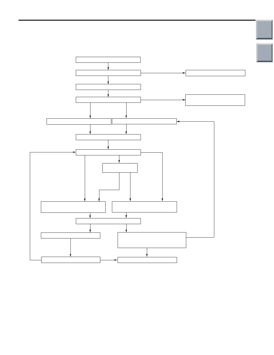
STANDARD FLOW OF DIAGNOSIS 
TROUBLESHOOTING

M1231213500090


OK

OK

NG

AC314016

NG

NG

OK

Ask about trouble symptoms

Check the CVT fluid

Check the trouble symptoms

Replace the CVT fluid

To INSPECTION CHART FOR
TROUBLE SYMPTOMS

Reading of a diagnosis code

Erase of a diagnosis code

Check the trouble symptoms

Inhibitor switch, TPS check

Road test

Recheck diagnosis 
codes

To INSPECTION CHART FOR
DIAGNOSIS CODES

To INSPECTION CHART FOR
TROUBLE SYMPTOMS

Check for the cause

Repair

Confirmation test (road test)

INTERMITTENT MALFUNCTIONS
(Refer to GROUP 00 - Points to
Note for Intermittent Malfunction)

Completed

Diagnosis code output
exists

No diagnosis code output

Abnormality exists 
(no diagnosis code output)

Abnormality exists 
(diagnostic trouble 
code output)

No abnormality

Found

Not found

Diagnosis code 
output exists

No diagnosis 
code output

Communication with the
MUT-III not possible

Communication with the
M.U.T.-III not possible

LEARNED VALUE INITIALIZATION 
PROCEDURE FOR CVT

M1231202400077

AIM

The use of EEPROM has enabled the CVT learned 
value to be retained even after the battery terminals 
are disconnected. However, the learned value should 
be initialised if the CVT assembly, the engine assem-
bly, the valve body assembly or the solenoid valves 
are replaced. The initialisation procedure is as 
below:

INITIALISATOIN PROCEDURE

1. Shift the selector lever to the P range and turn the 

ignition switch to the LOCK (OFF) position. Then, 
connect the M.U.T.-III to the diagnosis connector.

2. Initialise the learned value on the initialisation 

screen.

3. After this initialization, make the system learn the 

hydraulic pressure control in accordance with 
"CVT Fluid Pressure Control Learning 
Procedure."(Refer to 

P.23A-8

).

Main

Index

Group

TOC

TROUBLESHOOTING <CVT>

CVT

23A-8

NOTE: This reset procedure will also automatically 
initialize the INVECS-III Learned Value. CVT DTCs 
and CVT freeze-frame data will be erased. (Engine 
DTCs, engine-related freeze-frame data, and Readi-
ness status will remain even after CVT Learned 
Value is reset.)

CVT FLUID PRESSURE CONTROL 
LEARNING PROCEDURE

M1231225500053

AIM

If learned values are initialised, shift quality may be 
reduced. For how to make the system learn, follow 
the procedure below.

LEARN PROCEDURE

Step Item

Description

1

Engine idle learn.

Refer to GROUP 00 

− Precautions Before Service, 

Learning Procedure for Idling in MPI Engine 

P.00-21

.

2

CVT fluid cooling.

With the vehicle parked in the place with a relatively 
lower temperature, the vehicle should be left with the 
ignition switch turned OFF until the CVT fluid 
temperature is equal to the outside air temperature.

3

Learn in 
cold start.

(1) Measurement of CVT fluid 
temperature.

Measure the CVT fluid temperature using the 
M.U.T.-III. (Ensure that the CVT fluid temperature is 
equal to the outside air temperature).

(2) Garage shift learn.

CAUTION

When the selector lever is moved to N to D and N 
to R, the lever must be retained in the individual 
ranges for at least 2 seconds. Especially in the N 
range, the selector lever should be shifted to other 
ranges after the engine speed is stable. (Rapid 
shift operation may cause incorrect learning with 
the combined pressure as residual pressure and 
unstable engine speed).

• Start the engine, and move the selector lever to N 

to D and N to R two or three times respectively. 
When no shift shock is detected, this learn 
procedure will be completed.

• When a large shift shock is detected, repeat the 

same operation of N to D and N to R until no shift 
shock is detected (max.10 times each) to complete.

(3) Line pressure and shift 
control learn.

Move the selector lever to the D range, and let the 
engine run at idle for 20 seconds with the vehicle 
stationary.

(4) CVT fluid temperature 
adjustment

Increase CVT fluid temperature up to 40

°C.

(5) Direct-connection control 
learn.

Drive the vehicle for 5 seconds at 40 

− 50 km/h with the 

selector lever positioned in the D range.

Main

Index

Group

TOC

TROUBLESHOOTING <CVT>

CVT

23A-9

DIAGNOSIS FUNCTION

M1231219000101

N RANGE LAMP SYSTEM

AC509404AB

If there is a problem with any of the CVT system, the 
N range lamp will flash at a rate of approximately 
once per second.
If the N range lamp is flashing at a rate of approxi-
mately once per second, check the diagnosis output.
N RANGE LAMP FLASHING ITEM

Individual speed sensor systems
Line pressure sensor system
Primary pressure sensor system
Individual solenoid valve systems
Shift system
CVT control relay system
CVT fluid temperature sensor system

NOTE: If the "N" range lamp is flushing approxi-
mately twice per second, the CVT fluid temperature 
is high. (It flushes when the fluid is approximately 
145

°

C or more and goes off when the fluid is approx-

imately 135

°

C or less).

METHOD OF READING THE DIAGNOSIS 
CODE

Use the M.U.T.-III to read the diagnosis code (Refer 
to GROUP 00 

− How to Use Troubleshooting/Inspec-

tion Service Points 

P.00-7

).

METHOD OF ERASING THE DIAGNOSIS 
CODE

Use the M.U.T.-III to erase the diagnosis code (Refer 
to GROUP 00 

− How to Use Troubleshooting/Inspec-

tion Service Points 

P.00-7

).

FREEZE FRAME DATA CHECK

AC207750

Start of trouble judgment

Trouble 
confirma-
tion

Trouble 
judgment 
flag

Trouble 
confirma-
tion 
flag

Time

Trigger timing A

Trigger timing B

AB

10 ms

If the engine-CVT-ECU detects a malfunction and 
then sets a diagnosis code, it memorises the current 
CVT condition by obtaining the data which is created 
before (trigger timing A in the left figure) and when 
(trigger timing B) the diagnosis code is set. Trouble-
shooting can be carried out effectively by using the 
M.U.T.-III to analyse the data.

The freeze-frame data items are as follows.

4

Learn in hot 
start.

(1) CVT fluid temperature 
adjustment

CAUTION

When CVT fluid temperature is not increased up to 
80

°C in cold regions, this step should be 

performed after the CVT fluid temperature has 
been increased as high as possible.
Increase the CVT fluid temperature up to 80

°C.

(2) Garage shift learn*

Same as in cold start.

(3) Line pressure and shift 
control learn

Same as in cold start.

(4) Direct-connection control 
learn.

Same as in cold start.

Step Item

Description

Main

Index

Group

TOC

TROUBLESHOOTING <CVT>

CVT

23A-10

Data Item List

Item No.

M.U.T.-III Display

Data item

Unit

01

CRANK A. SNSR

Crank angle sensor

r/min

02

TURBIN SPEED

Turbine speed sensor

r/min

03

PRIMARY SPEED

Primary speed sensor

r/min

04

2NDARY SPEED

Secondary speed sensor

r/min

06

APS

Accelerator pedal position sensor (APS)

mV

07

INFO. Pe1

Engine target average effective pressure

MPa

08

OIL TEMP. SNSR

CVT fluid temperature sensor

°C

09

LINE PRESS.

Line pressure sensor

MPa

11

PRIMARY PRESS

Primary pressure sensor

MPa

13

INFO. Pe2

Engine output average effective pressure

MPa

14

DCC SOL. DUTY

Duty ratio of damper clutch control solenoid

%

15

SHIFT SOL. D.

Duty ratio of shift control solenoid

%

16

LINE SOL. DUTY

Duty ratio of line pressure control solenoid

%

17

CLUTCH SOL. D.

Duty ratio of clutch pressure control solenoid

%

26

INHIBITOR SW

Inhibitor switch

33

STOP LAMP SW

Stop lamp switch

36

INFO. PRM. PRS

Target primary pressure

MPa

38

INFO. LINE. PRS.

Target line pressure

MPa

3B

INFO. PRM. REV.

Target primary speed

r/min

ROAD TEST

M1231207800111

Proce
dure

Pre-test/


operation 
conditions

Test/Operation

Judgment value

Check item Diagnosis 

code No.

Inspection 
procedure if there is 
an abnormality

1

Ignition switch: 
LOCK (OFF) 
position

Ignition switch

(1) ON

Data List No.25

(1) System 

voltage [V]

CVT 
control 
relay

56

CVT control relay 
system

2

• Ignition 

switch: ON

• Engine: 

Stopped

Selector lever 
position

(1) P 
(2) R
(3) N 
(4) D
(5) Ds
(6) L

Data List No.26

(1) P 
(2) R
(3) N 
(4) D
(5) Ds
(6) L

Inhibitor 
switch

51, 52

Inhibitor switch 
system

Main

Index

Group

TOC


Content   ..  164  165  166  167   ..