Mitsubishi Colt Ralliart. Manual - part 132
EMISSION CONTROL
ENGINE AND EMISSION CONTROL
17-19
<From Jun. 2006 models>
AC600433AB
1
2
3
4
5
7
6
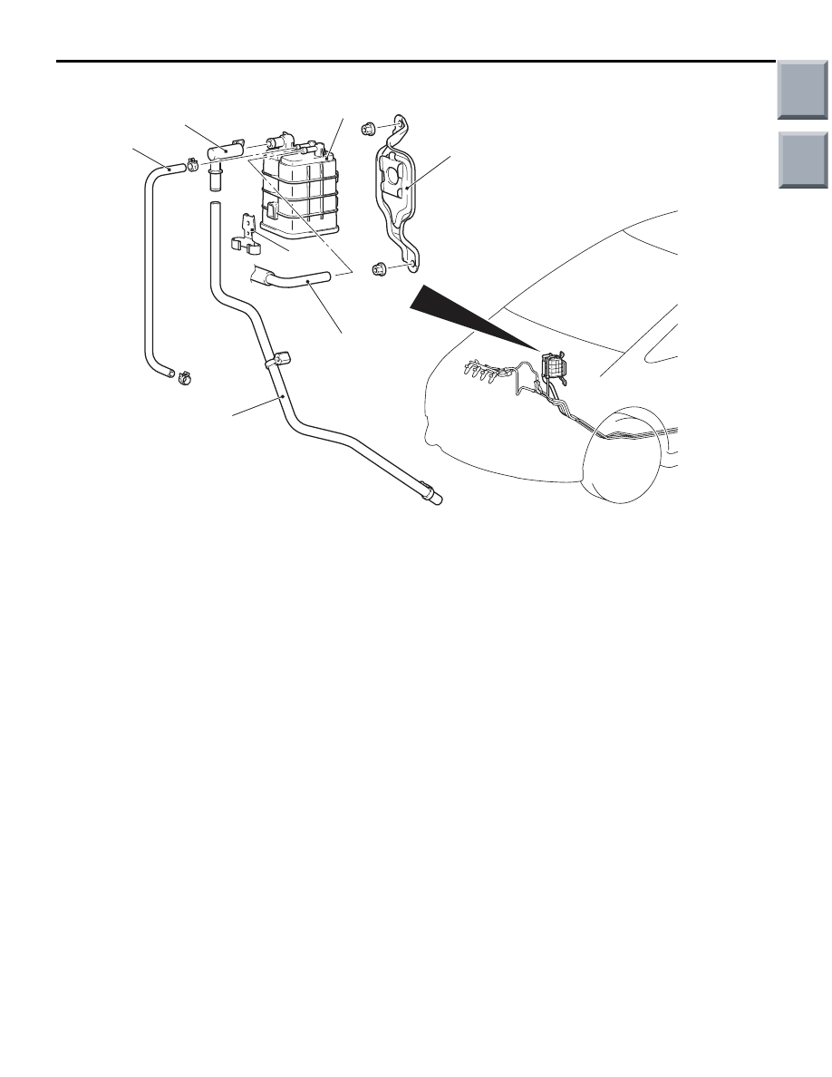
Removal steps
1.
Purge hose connection
2.
Vapour hose
3.
Vent connector
4.
Vapour hose
5.
Canister
6.
Clamp
7.
Canister bracket
EXHAUST GAS RECIRCULATION (EGR) VALVE
GENERAL INFORMATION (EGR SYSTEM)
<4A9-CVT>
M1173005200822
The exhaust gas recirculation (EGR) system lowers
the nitrogen oxide (NOx) emission level.
When the air/fuel mixture combustion temperature is
high, a large quantity of nitrogen oxides (NOx) is
generated in the combustion chamber.
Therefore, this system recirculates part of emission
gas from the exhaust port of the cylinder head to the
combustion chamber through the inlet manifold to
decrease the air/fuel mixture combustion tempera-
ture, resulting in reduction of NOx.
The EGR flow rate is controlled by the EGR valve so
as not to decrease the driveability.
OPERATION
The EGR valve is being closed and does not recircu-
late exhaust gases under one of the following condi-
tions.
Otherwise, the EGR valve is opened and recirculates
exhaust gases.
• The engine coolant temperature is low.
• The engine is at idle.
• The throttle valve is widely opened.
Removal steps (Continued)
Main
Index
Group
TOC