Mitsubishi Colt Ralliart. Manual - part 125
IGNITION SYSTEM
ENGINE ELECTRICAL
16-34
SPARK PLUG SPECIFICATIONS
Item
Specification
BOSCH <4A9>
FR7SI30
NGK <4G1>
IZFR6C-K
SERVICE SPECIFICATIONS
M1163000300373
SPARK PLUG
Item
Standard value
Limit
Spark plug gap mm
4A9
1.0
− 1.1
1.4
4G1
0.7
− 0.8
0.95
SEALANT <4A9>
M1163000500043
Item
Specified sealant
Remark
Cylinder block
LOCTITE 5971 or exact equivalent
Semi-drying sealant
ON-VEHICLE SERVICE
IGNITION COIL (WITH BUILT-IN POWER TRANSISTOR) CHECK
M1163001200711
Check by the following procedure, and replace if
there is a malfunction.
PRIMARY COIL AND POWER TRANSIS-
TOR CONTINUITY CHECK
NOTE:
.
•
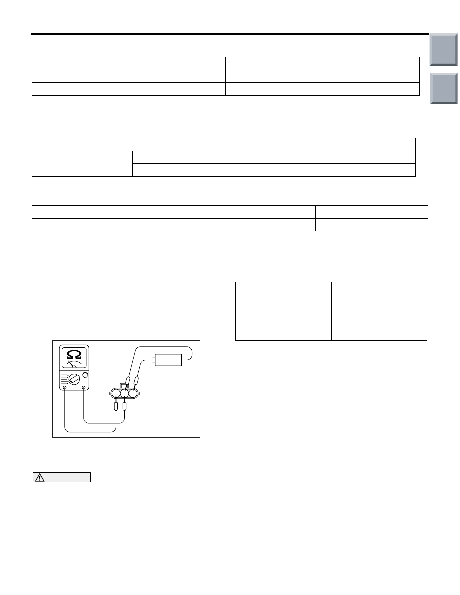
AK202356
1 2 3
AG
4.5 – 9.0 V
–
+
–
+
An analogue-type circuit tester should be used.
•
Connect the negative (-) prove of the circuit tester
to terminal No. 1.
CAUTION
This test must be performed quickly (in less
than 10 seconds) to prevent coil from burning
and power transistor from breakage.
Connect and disconnect 4.5
− 9.0 V battery between
terminal No. 2 and No. 3, and observe the ohmmeter
whether there is continuity or not.
4.5
− 9.0 V power
supply between 2
− 3
Continuity between
1
− 2
When current is flowing
Continuity
When current is not
flowing
No continuity
SECONDARY COIL CHECK
NOTE: It is impossible to check the secondary coil
through the continuity check as a diode is integrated
in the secondary coil circuit of this ignition coil.
Accordingly, check the secondary coil in the following
procedure.
1. Disconnect the ignition coil connector.
2. Remove the ignition coil and install a good spark
plug to the ignition coil.
3. Connect the ignition coil connector.
4. Earth the side electrode of the spark plug and
crank the engine.
5. Check that spark is produced between the
electrodes of the spark plug.
6. If no spark plug is produced, replace the ignition
coil with a good one and recheck.
7. If spark is produced with the good ignition coil,
replace the old one as it is faulty. If no spark is
produced again, the ignition circuit is suspected
as faulty. Check the ignition circuit.
Main
Index
Group
TOC