Mitsubishi Colt Ralliart. Manual - part 124


  Index      Mitsubishi     Mitsubishi Colt Ralliart - service repair manual


Search            


Content   ..  122  123  124  125   ..


Mitsubishi Colt Ralliart. Manual - part 124


STARTING SYSTEM

ENGINE ELECTRICAL

16-30

DISASSEMBLY SERVICE POINTS
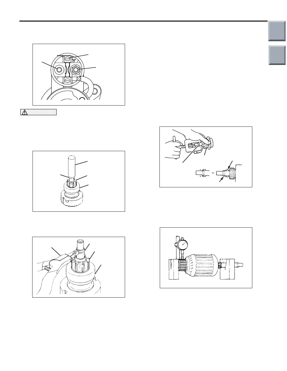
<<A>> MAGNETIC SWITCH REMOVAL

AK201882

B terminal

M terminal

S terminal

AC

CAUTION

Do not clamp the yoke assembly with a vise.
Disconnect the lead from the M terminal of the mag-
netic switch.

<<B>> SNAP RING/STOP RING REMOVAL

AK202790

Socket wrench

Stop ring

Pinion Gear

Overrunning 
clutch

AB

1. Apply a long socket wrench of an appropriate size 

to the stop ring and strike the wrench to drive out 
the stop ring toward the pinion gear side.

AK202791

Snap ring 
pliers

Snap ring

Pinion gear

Overrunning 
clutch

AB

2. Remove the snap ring with snap ring pliers, then 

remove the stop ring and overrunning clutch.

STARTER MOTOR PARTS CLEANING

Never clean in a solvent such starter motor parts as 

the magnetic switch, brush holder, and armature. 
If they are soaked in a solvent, their insulation 
could be impaired. When these parts require 
cleaning, wipe off contamination with cloth.

1. Never soak the drive unit in a solvent. If it is 

washed in a solvent, the grease having been 
packed in the overrunning clutch at the factory will 
be washed out. Wipe the drive unit with cloth if it 
requires cleaning.

REASSEMBLY SERVICE POINTS
>>A<< STOP RING/SNAP RING INSTAL-
LATION

AK202911

Overrunning 
clutch

Stop ring

Snap ring

Stop ring

AB

Use a suitable puller to pull the stop ring until it gets 
over the snap ring.

INSPECTION 

M1162001300265

COMMUTATOR

AK202712

1. Support the armature with a pair of V block and 

turn it to measure the runout of the surface not 
rubbed by the brushes using a dial gauge.

Standard value: 0.02 mm or less
Limit: 0.05 mm

Main

Index

Group

TOC

AK202715

STARTING SYSTEM

ENGINE ELECTRICAL

16-31

2. Measure the diameter of the commutator.

Standard value: 29.4 mm
Limit: 28.8 mm

AK202711

Segment

Undercut

Mica

AB

3. Measure the depth of the undercut between 

segments.

Standard value: 0.5 mm
Limit: 0.2 mm

BRUSH HOLDER

AK201187

Push the brush into the brush holder to make sure 
that the spring is working on the brush.
If the spring is not working, replace the brush holder.

OVERRUNNING CLUTCH

AK202710

Free

Lock

AB

1. Make sure that the pinion cannot be turned 

counterclockwise and can be turned clockwise 
freely.

2. Check the pinion for abnormal ware and damage.

BRUSHES

AK202846

Brush 
height

AB

1. Check the commutator contacting surface of each 

brush for abnormal roughness. Also check the 
height of the brush. Replace the brush holder if 
the height is lower than the limit.

Limit: 5.5 mm

2. When the contact surface of the brush is rectified 

or the brush holder is replaced, recondition the 
contact surface with sandpaper wrapped around 
the commutator.

Main

Index

Group

TOC

STARTING SYSTEM

ENGINE ELECTRICAL

16-32

ARMATURE COIL

1. Check the armature coil for short circuit as 

follows:

AK202733

Growler

AB

2. Set the armature in a growler.

CAUTION

Clean the surface of the armature thoroughly 
before performing the test.
3. While holding a thin strip of iron against the 

armature in parallel with its axis, turn the armature 
slowly. The armature is normal if the iron strip is 
not attracted to the armature or it does not vibrate.

AK202734

4. Check the insulation between commutator 

segments and armature coils. The armature coils 
are properly insulated if no continuity is present.

AK202713

5. Check continuity between a segment and another. 

There is no open circuit in the tested coil if there is 
continuity.

MAGNETIC SWITCH

AK202891

A

M  terminal

AB

1. Coil open circuit test

• Check that there is continuity between the M ter-

minal and body A.

AK202892

M terminal

B terminal

AB

If there is no continuity, replace the magnetic 
switch.

2. Contact fusion check

• Check that there is no continuity between the B 

terminal and M terminal.

AK202893

M terminal

B terminal

AB

If there is continuity, replace the magnetic switch.

3. Switch contact check

• Push the indicated end of the magnetic switch 

with a strong force to close the internal contacts. 
Without releasing the switch end, check that 
there is continuity between the B terminal and M 
terminal.

• If there is no continuity, replace the magnetic 

switch.

Main

Index

Group

TOC

IGNITION SYSTEM

ENGINE ELECTRICAL

16-33

IGNITION SYSTEM

GENERAL INFORMATION

M1163000100711

This system is equipped with four ignition coils with 
built-in power transistors for each of the cylinders.
Interruption of the primary current flowing in the pri-
mary side of an ignition coil generates a high voltage 
in the secondary side of ignition coil. The high volt-
age thus generated is applied to the spark plugs to 
generate sparks. The engine-ECU <M/T> or 
engine-CVT-ECU <CVT> turns the power transistors 
inside the ignition coils alternately on and off.This 
causes the primary currents in the ignition coils to be 
alternately interrupted and allowed to flow to fire the 
cylinders in the order 1-3-4-2.

The engine-ECU <M/T> or engine-CVT-ECU <CVT> 
determines which ignition coil should be controlled 
by means of the signals from the camshaft position 
sensor and the crank angle sensor. It also detects 
the crankshaft position, in order to provide ignition at 
the most appropriate timing in response to the 
engine operation conditions.
When the engine is cold or running at high altitudes, 
the ignition timing is slightly advanced to provide 
optimum performance. Furthermore, if knocking 
occurs, the ignition timing is gradually retarded until 
knocking ceases.

SYSTEM DIAGRAM

AK600740

Manifold absolute pressure
sensor <4A9>

Air flow sensor <4G1>

Intake air temperature 
sensor

Engine coolant temperature 
sensor

Accelerator pedal position 
sensor

Camshaft position sensor

Crank angle sensor

Detonation sensor

Clutch switch <4G1>

Ignition switch-ST

Engine-ECU

<M/T>

or

Engine-CVT

-ECU <CVT>

Ignition coil

Cylinder No.

1

2

3

AB

4

Spark plug

Ignition
switch

Battery

IGNITION COIL SPECIFICATION

Item

Specification

Type

Molded 4-coil

Main

Index

Group

TOC


Content   ..  122  123  124  125   ..