Mitsubishi Colt Ralliart. Manual - part 102


  Index      Mitsubishi     Mitsubishi Colt Ralliart - service repair manual


Search            


Content   ..  100  101  102  103   ..


Mitsubishi Colt Ralliart. Manual - part 102


ON-VEHICLE SERVICE

MULTIPORT FUEL INJECTION (MPI) <4A9>

13A-362

ENGINE COOLANT TEMPERATURE 
SENSOR CHECK

M1131003101156

CAUTION

Be careful not to touch the connector (resin sec-
tion) with the tool when removing and installing.

1. Remove the engine coolant temperature sensor 

using coolant temperature sensor wrench, special 
tool (MB992042).

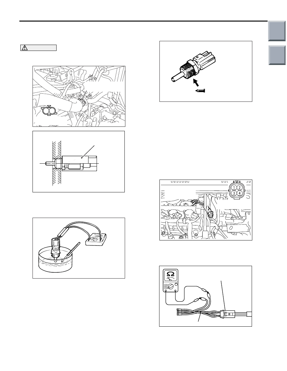
2. With temperature sensing portion of engine 

coolant temperature sensor immersed in hot 
water, check resistance.

Standard value:

14 

 17 k (at 20°C)

5.1 

 6.5 k (at 0°C)

2.1 

 2.7 k (at 20°C)

0.9 

 1.3 k (at 40°C)

0.48 

 0.68 k (at 60°C)

0.26 

 0.36 k (at 80°C)

3. If the resistance deviates from the standard value 

greatly, replace the sensor.

4. Apply sealant to threaded portion.

Specified sealant:

LOCTITE 262 or equivalent

5. Tighten the engine coolant temperature sensor to 

the specified torque, using coolant temperature 
sensor wrench, special tool (MB992042)

Tightening torque: 29 

± 10 Nm

OXYGEN SENSOR CHECK

M1131005001627

OXYGEN SENSOR (FRONT)

1. Disconnect the oxygen sensor connector and 

connect the special tool Test harness (MB991658) 
to the connector on the oxygen sensor side.

2. Make sure that there is continuity (5 

− 30 Ω at 

20

°C) between terminal No. 3 and No. 4 on the 

oxygen sensor connector.

AK402201

1 2

Engine coolant
temperature sensor

AC

Equipment side
connector

AK503116 AC

MB992042

AKX01622

AKX01623AD

AK402203

AC

Equipment side
connector

Oxygen sensor
(front) connector

AK101798

MB991658

AG

Oxygen sensor 
side connector

Main

Index

Group

TOC

ON-VEHICLE SERVICE

MULTIPORT FUEL INJECTION (MPI) <4A9>

13A-363

3. If there is no continuity, replace the oxygen 

sensor.

4. Warm up the engine until engine coolant is 80

°C 

or higher.

5. Perform a tracing for 5 minutes or more with the 

engine speed of 4,500 r/min.

6. Connect a digital voltage meter between terminal 

No. 1 and No. 2.

7. While repeatedly racing the engine, measure the 

oxygen sensor output voltage.

Standard value:

CAUTION

• Be very careful when connecting the jumper 

wire; incorrect connection can damage the 
oxygen sensor.

• Be careful the heater is broken when voltage 

of beyond 8V is applied to the oxygen sensor 
heater.

NOTE: If the sufficiently high temperature (of 
approximate 400

°

C or more) is not reached 

although the oxygen sensor is normal, the output 
voltage would be possibly low although the rich 
air-fuel ratio. Therefore, if the output voltage is 
low, use a jumper wire to connect the terminal 
No.3 and the terminal No. 4 of the oxygen sensor 
with a (+) terminal and (

) terminal of 12 V power 

supply respectively, then check again.

8. If the sensor is defective, replace the oxygen 

sensor.

NOTE: For removal and installation of the oxygen 
sensor, refer to GROUP 15 

 Exhaust Pipe and 

Main Muffler 

 Exhaust Pipe and Main Muffler 

Removal and installation 

P.15-19

.

OXYGEN SENSOR (REAR)

1. Disconnect the oxygen sensor connector and 

connect the special tool Test harness (MB991658) 
to the connector on the oxygen sensor side.

2. Make sure that there is continuity (5 

− 30 Ω at 

20

°C) between terminal No. 3 and No. 4 on the 

oxygen sensor connector.

3. If there is no continuity, replace the oxygen 

sensor.

4. Warm up the engine until engine coolant is 80

°C 

or higher.

5. Perform a tracing for 5 minutes or more with the 

engine speed of 4,500 r/min.

Engine

Oxygen 
sensor 
output 
voltage

Remarks

When 
racing the 
engine

0.6 

− 1.0 V If you make the air-fuel 

ratio rich by racing the 
engine repeatedly, a 
normal oxygen sensor 
will output a voltage of 
0.6 

− 1.0 V.

AK402649

MB991658

AD

Oxygen sensor 
Equipment side connector

AK403439

2

1

3 4

AC

Equipment side connector

Oxygen sensor (rear)

Oxygen sensor (rear) connector

AK402205

MB991658

AC

Oxygen sensor side 
connector

Main

Index

Group

TOC

ON-VEHICLE SERVICE

MULTIPORT FUEL INJECTION (MPI) <4A9>

13A-364

6. Connect a digital voltage meter between terminal 

No.1 and No. 2.

7. While repeatedly racing the engine, measure the 

oxygen sensor output voltage.

Standard value:

CAUTION

• Be very careful when connecting the jumper 

wire; incorrect connection can damage the 
oxygen sensor.

• Be careful the heater is broken when voltage 

of beyond 12 V is applied to the oxygen sen-
sor heater.

NOTE: If the sufficiently high temperature (of 
approximate 400

°

C or more) is not reached 

although the oxygen sensor is normal, the output 
voltage would be possibly low although the rich 
air-fuel ratio. Therefore, if the output voltage is 
low, use a jumper wire to connect the terminal No. 
3 and the terminal No. 4 of the oxygen sensor with 
a (+) terminal and (

) terminal of 12 V power sup-

ply respectively, then check again.

8. If the sensor is defective, replace the oxygen 

sensor.
NOTE: . For removal and installation of the oxy-
gen sensor, refer to GROUP 15 

 Exhaust Pipe 

and Main Muffler 

 Exhaust Pipe and Main Muffler 

Removal and installation 

P.15-19

.

INJECTOR CHECK

M1131005201416

CHECK THE OPERATION SOUND

1. Use a stethoscope to listen to the operation sound 

(clicking) of the injectors while the engine is idling 
or cranking.

CAUTION

Beware that the operation sounds of other injec-
tors can be heard even if the injector that is being 
inspected might not be operating.
2. Verify that the operation sound increases with the 

engine speed.
NOTE: If the operating sound cannot be heard, 
inspect the injector actuation circuit.

MEASUREMENT OF RESISTANCE 
BETWEEN TERMINALS

1. Disconnect the injector connector.
2. Measure the resistance between terminals.

Standard value: 14 

 15  (at 20°C)

3. Connect the injector connector.

Engine

Oxygen 
sensor 
output 
voltage

Remarks

When 
racing the 
engine

0.6 

− 1.0 V If you make the air-fuel 

ratio rich by racing the 
engine repeatedly, a 
normal oxygen sensor 
will output a voltage of 
0.6 

− 1.0 V.

AK402650

MB991658

AC

Oxygen sensor
Equipment side connector

AK402289

1 2

AC

Injector 
equipment side
connector

Injector

Main

Index

Group

TOC

ON-VEHICLE SERVICE

MULTIPORT FUEL INJECTION (MPI) <4A9>

13A-365

CHECK THE INJECTION CONDITION

1. Carry out the procedure to prevent flow of the fuel 

(Refer to 

P.13A-357

).

CAUTION

Do not make fuel splash by covering fuel with 
waste and so on because the residual pressure is 
in the fuel pipeline.
2. Remove the fuel high-pressure hose at the 

delivery pipe side.

3. Remove the injector.
4. Assemble Injector Test Set (MB992076 or 

MD998706) of the special tool as shown in Fig.

a. Remove the installation hose for the injector.
b. Install the injector to the installation hose for the 

injector and then fix it using Injector Holder 
(MB991976) of the special tool.

5. Install the special tool hose adapter (MB992001) 

to the installation hose for the injector and connect 
them to the fuel high-pressure hose.

6. Connect the M.U.T.-III to the diagnosis connector.
7. Turn the ignition switch to "ON" position (but do 

not start the engine).

8. Select "Item No. 07" from M.U.T.-III actuator test 

and drive the fuel pump.

9. Connect Injector Test Harness (MB991607) of the 

special tool between the injector and battery, and 
then actuate the injector.

10.Check the fuel spray condition. The condition can 

be considered satisfactory unless it is extremely 
poor.

11.Stop actuating the injector. Check leakage from 

the injector nozzle. Turn the ignition switch to 
"LOCK OFF" position and then disconnect 
M.U.T.-III.

12.Actuate the injector until the fuel cannot flow. 

Draw the fuel out from the special tool.

13.Remove the special tool.
14.If the fuel spray condition is extremely poor or if 

there is the fuel leakage from the injector nozzle, 
replace the injector.

15.Install the injector and fuel high-pressure hose.

OIL FEEDER CONTROL VALVE CHECK

M1131053800050

OPERATION CHECK

1. Disconnect the oil feeder control valve connector.

CAUTION

To prevent the coil from burning, keep the dura-
tion of the voltage application as short as possi-
ble.
2. Apply battery voltage to the terminals of the 

connector at the oil feeder control valve, and 
make sure the oil feeder control valve makes a 
clicking sound.

AK402078AD

MB991976

Injector

MB992076
or
MD998706

AK402079AE

MB991976

MB992001

MB992076
or
MD998706

Fuel 
high-pressure
hose

Injector

AK402080AC

MB991607

AK402207

1 2

AC

Oil feeder 
control valve

Oil feeder 
control valve side
connector

Main

Index

Group

TOC


Content   ..  100  101  102  103   ..