Mitsubishi Colt Ralliart. Manual - part 101


  Index      Mitsubishi     Mitsubishi Colt Ralliart - service repair manual


Search            


Content   ..  99  100  101  102   ..


Mitsubishi Colt Ralliart. Manual - part 101


ON-VEHICLE SERVICE

MULTIPORT FUEL INJECTION (MPI) <4A9>

13A-358

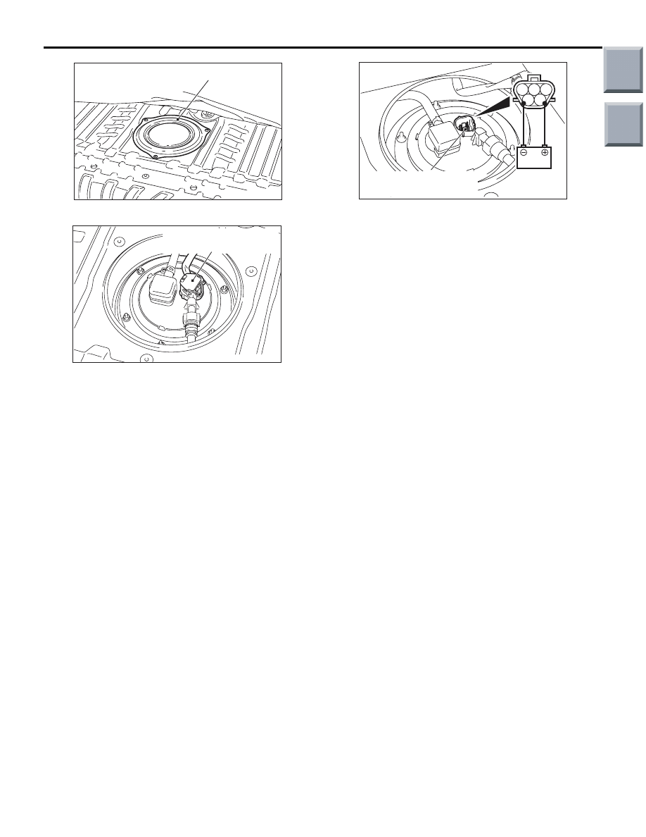
(4) Remove the service hole cover.

(5) Disconnect the fuel tank pump and gauge 

assembly connector.

(6) Remove the fuel tank cap.

(7) When the fuel tank pump and gauge assembly 

connector terminal is connected directly to the 
battery, check if the sound of the fuel tank 
pump operation can be heard. If no operating 
sound is heard, replace the fuel tank pump 
(Refer to GROUP 13C, On-vehicle Service 

P.13C-3

).

NOTE: As the fuel tank pump is an in-tank 
type, the fuel tank pump sound is hard to hear. 
Then check the sound from the tank inlet.

(8) Install the fuel tank cap.
(9) Check for fuel pressure by pinching the fuel 

hose with fingertips.

(10)Connect the fuel tank pump and gauge 

assembly connector.

(11)Install the service hole cover.
(12)Return the floor carpet to the original state, 

and install the rear scuff plate. (Refer to 
GROUP 52A, Interior Trims 

P.52A-11

).

(13)Return the rear seat assembly to the original 

state.

AC207365AD

Service hole cover

AC400103AB

Fuel tank pump and
gauge assembly connector

1 2 3

4 5

AC207376AC

Fuel tank pump and
gauge assembly connector

Main

Index

Group

TOC

ON-VEHICLE SERVICE

MULTIPORT FUEL INJECTION (MPI) <4A9>

13A-359

COMPONENT LOCATION

M1131002101788

Name

Symbol

Name

Symbol

Accelerator pedal position sensor

M

Engine control relay

J

A/C relay

J

Engine coolant temperature sensor

D

Camshaft position sensor

F

Fuel pump relay

J

Crank angle sensor

H

Ignition coil

B

Detonation sensor

H

Injector

B

Diagnosis connector

G

Manifold absolute pressure sensor

I

EGR valve <CVT>

I

Oil feeder control valve

A

Electronic-controlled throttle valve 
(Throttle position sensor and throttle 
valve control servo)

I

Oxygen sensor (front)

C

Engine-ECU <M/T> or engine-CVT-ECU 
<CVT> (with barometric pressure sensor)

G

Oxygen sensor (rear)

N

Purge control solenoid valve

E

Stop lamp switch

K

Throttle valve control servo relay

J

AK503633

A

H

I

L

M

B

C

D

E

F

G

J

K

N

AB

Main

Index

Group

TOC

ON-VEHICLE SERVICE

MULTIPORT FUEL INJECTION (MPI) <4A9>

13A-360

ENGINE CONTROL RELAY CONTINUITY 
CHECK

M1131050000903

FUEL PUMP RELAY CONTINUITY CHECK

M1131033000922

Tester 
Connection 
Terminal

Battery Voltage

Normal State

− 2

No voltage

Continuity (2 
Ω or less)

− 4

No voltage

No continuity

Voltage (Connect 
positive (+) terminal of 
battery to terminal No. 1 
and negative (

−) terminal 

of battery to terminal 
No. 2.)

Continuity (2 
Ω or less)

AK600543

3

1

2

4

AB

Relay side
connector

J/B (front side)

Engine 
control relay

Fuel pump relay 2

Fuel pump relay 1

Throttle valve 
control servo 
relay

Tester 
Connection 
Terminal

Battery Voltage

Normal State

− 2

No voltage

Continuity (2 
Ω or less)

− 4

No voltage

No continuity

Voltage (Connect 
positive (+) terminal of 
battery to terminal No. 1 
and negative (

−) terminal 

of battery to terminal 
No. 2.)

Continuity (2 
Ω or less)

AK600543

3

1

2

4

AB

Relay side
connector

J/B (front side)

Engine 
control relay

Fuel pump relay 2

Fuel pump relay 1

Throttle valve 
control servo 
relay

Main

Index

Group

TOC

ON-VEHICLE SERVICE

MULTIPORT FUEL INJECTION (MPI) <4A9>

13A-361

THROTTLE VALVE CONTROL SERVO 
RELAY CONTINUITY CHECK

M1131053500264

INTAKE AIR TEMPERATURE SENSOR 
CHECK

M1131002800955

1. Disconnect the manifold absolute pressure 

sensor.

2. Measure resistance between terminals No. 3 and 

No. 4.

Standard value:

13 

 17 k (at 20°C)

5.3 

 6.7 k (at 0°C)

2.3 

 3.0 k (at 20°C)

1.0 

 1.5 k (at 40°C)

0.56 

 0.76 k (at 60°C)

0.30 

 0.42 k (at 80°C)

3. Remove the manifold absolute pressure sensor.

4. Measure resistance while heating the sensor 

using a hair drier.

Normal condition:

5. If the value deviates from the standard value or 

the resistance remains unchanged, replace the 
manifold absolute pressure sensor assembly.

6. Install the manifold absolute pressure sensor and 

tighten it to the specified torque.

Tightening torque: 6.0 

± 0.5 Nm

Tester 
Connection 
Terminal

Battery Voltage

Normal State

− 2

No voltage

Continuity (2 
Ω or less)

− 4

No voltage

No continuity

Voltage (Connect 
positive (+) terminal of 
battery to terminal No. 1 
and negative (

−) terminal 

of battery to terminal 
No. 2.)

Continuity (2 
Ω or less)

AK600543

3

1

2

4

AB

Relay side
connector

J/B (front side)

Engine 
control relay

Fuel pump relay 2

Fuel pump relay 1

Throttle valve 
control servo 
relay

Temperature (

°C)

Resistance (k

)

Higher

Smaller

AK402199

1

2

3 4

Manifold absolute pressure sensor 
(with built-in intake air temperature sensor)

AC

Intake air temperature 
sensor 
Equipment side connector

AK402200

Intake air 
temperature 
sensor

AC

Main

Index

Group

TOC


Content   ..  99  100  101  102   ..