Mitsubishi Colt Ralliart. Manual - part 46


  Index      Mitsubishi     Mitsubishi Colt Ralliart - service repair manual


Search            


Content   ..  44  45  46  47   ..


Mitsubishi Colt Ralliart. Manual - part 46


TROUBLESHOOTING

MULTIPORT FUEL INJECTION (MPI) <4A9>

13A-138

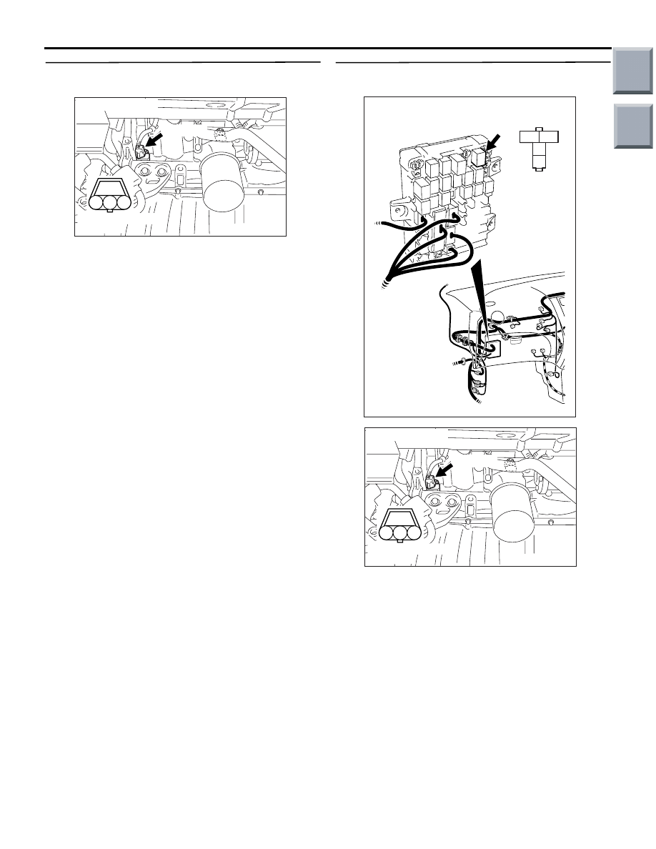
STEP 9. Perform voltage measurement at A-133 
crank angle sensor connector.

• Disconnect connector, and measure at harness 

side.

• Ignition switch: ON 

• Voltage between terminal No. 3 and earth.

OK: System voltage

Q: Is the check result normal? 

YES : 

Go to Step 11 .

NO : 

Go to Step 10 .

STEP 10. Connector check: B-106 engine control 
relay connector

Q: Is the check result normal? 

YES : 

Check intermediate connector A-17 and 

B-112, and repair if necessary. If 
intermediate connectors are normal, check 
and repair harness between A-133 (terminal 
No. 3) crank angle sensor connector and 
B-106 (terminal No. 4) engine control relay 
connector.

• Check power supply line for 

open/short circuit.

NO : 

Repair or replace the connector.

AK402016

1

2

3

AC

Connector: A-133

A-133 (B)

A-133 Harness side 
connector

3

2

1

4

AK402060

B-106
J/B side 
connector

B-106

Connector: B-106
J/B (front side)

AC

AK402016

1

2

3

AC

Connector: A-133

A-133 (B)

A-133 Harness side 
connector

Main

Index

Group

TOC

TROUBLESHOOTING

MULTIPORT FUEL INJECTION (MPI) <4A9>

13A-139

STEP 11. Perform resistance measurement at 
A-133 crank angle sensor connector.

• Disconnect connector, and measure at harness 

side.

• Resistance between terminal No. 1 and earth.

OK: Continuity (2 

 or less)

Q: Is the check result normal? 

YES : 

Go to Step 15 .

NO : 

Go to Step 12 .

STEP 12. Connector check: A-114 engine-ECU 
connector or engine-CVT-ECU connector

Q: Is the check result normal? 

YES : 

Go to Step 13 .

NO : 

Repair or replace the connector.

STEP 13. Check harness between A-133 (terminal 
No. 1) crank angle sensor connector and A-114 
(terminal No. 28) engine-ECU connector or 
engine-CVT-ECU connector.

• Check earthing line for open circuit and damage.

Q: Is the check result normal? 

YES : 

Go to Step 14 .

NO : 

Repair the damaged harness wire.

STEP 14. M.U.T.-III data list

• Refer to Data List Reference Table 

P.13A-331

.

a. Item 22: Crank angle sensor 

Q: Is the check result normal? 

YES : 

Intermittent malfunction (Refer to GROUP 

00 

− How to Use Troubleshooting/Inspection 

Service Points 

− How to Cope with 

Intermittent Malfunctions 

P.00-13

).

NO : 

Replace crank angle sensor.

AK402016

1

2

3

AC

Connector: A-133

A-133 (B)

A-133 Harness side 
connector

AK402745

6

4

2

5

3

1

9

7

8

10

11

12

13

14

15

16

17

18

19

20

21

22

23

24

25

26

27

28

29

30

31

32

33

34

35

36

37

38

39

40

41

42

43

44

45

46

47

48

49

50

51

52

53

54

55

56

57

58

59

60

61

62

63

64

65

66

L

AD

A-114

Connector: 

A-114

Harness side connector

Engine-ECU <M/T> or
engine-CVT-ECU <CVT>

Battery

Main

Index

Group

TOC

TROUBLESHOOTING

MULTIPORT FUEL INJECTION (MPI) <4A9>

13A-140

STEP 15. Perform output wave pattern 
measurement at A-133 crank angle sensor 
connector (Using an oscilloscope).

• Use special tool test harness (MB991709) to con-

nect connector, and measure at pick-up harness.

• Engine: Idling

• Transmission: P range

• Voltage between terminal No. 2 and earth.

OK: Waveforms should be displayed on 
Inspection procedure using an oscilloscope 
(Refer to 

P.13A-348

), its maximum value 

should be 4.8 V or more, and its minimum 
value should be 0.6 V or less with no noise in 
waveform.

Q: Is the check result normal? 

YES : 

Go to Step 21 .

NO : 

Go to Step 16 .

STEP 16. Connector check: B-106 engine control 
relay connector

Q: Is the check result normal? 

YES : 

Go to Step 17 .

NO : 

Repair or replace the connector.

AK402016

1

2

3

AC

Connector: A-133

A-133 (B)

A-133 Harness side 
connector

3

2

1

4

AK402060

B-106
J/B side 
connector

B-106

Connector: B-106
J/B (front side)

AC

Main

Index

Group

TOC

TROUBLESHOOTING

MULTIPORT FUEL INJECTION (MPI) <4A9>

13A-141

STEP 17. Check harness between A-133 (terminal 
No. 3) crank angle sensor connector and B-106 
(terminal No. 4) engine control relay connector.

NOTE: Before checking harness, check intermediate 
connector A-17 and B-112, and repair if necessary. 

• Check power supply line for damage.

Q: Is the check result normal? 

YES : 

Go to Step 18 .

NO : 

Repair the damaged harness wire.

STEP 18. Connector check: A-114 engine-ECU 
connector or engine-CVT-ECU connector

Q: Is the check result normal? 

YES : 

Go to Step 19 .

NO : 

Repair or replace the connector.

AK402016

1

2

3

AC

Connector: A-133

A-133 (B)

A-133 Harness side 
connector

3

2

1

4

AK402060

B-106
J/B side 
connector

B-106

Connector: B-106
J/B (front side)

AC

AK402745

6

4

2

5

3

1

9

7

8

10

11

12

13

14

15

16

17

18

19

20

21

22

23

24

25

26

27

28

29

30

31

32

33

34

35

36

37

38

39

40

41

42

43

44

45

46

47

48

49

50

51

52

53

54

55

56

57

58

59

60

61

62

63

64

65

66

L

AD

A-114

Connector: 

A-114

Harness side connector

Engine-ECU <M/T> or
engine-CVT-ECU <CVT>

Battery

Main

Index

Group

TOC


Content   ..  44  45  46  47   ..