Mitsubishi Colt Ralliart. Manual - part 44


  Index      Mitsubishi     Mitsubishi Colt Ralliart - service repair manual


Search            


Content   ..  42  43  44  45   ..


Mitsubishi Colt Ralliart. Manual - part 44


TROUBLESHOOTING

MULTIPORT FUEL INJECTION (MPI) <4A9>

13A-130

Code No. P0325: Detonation Sensor System
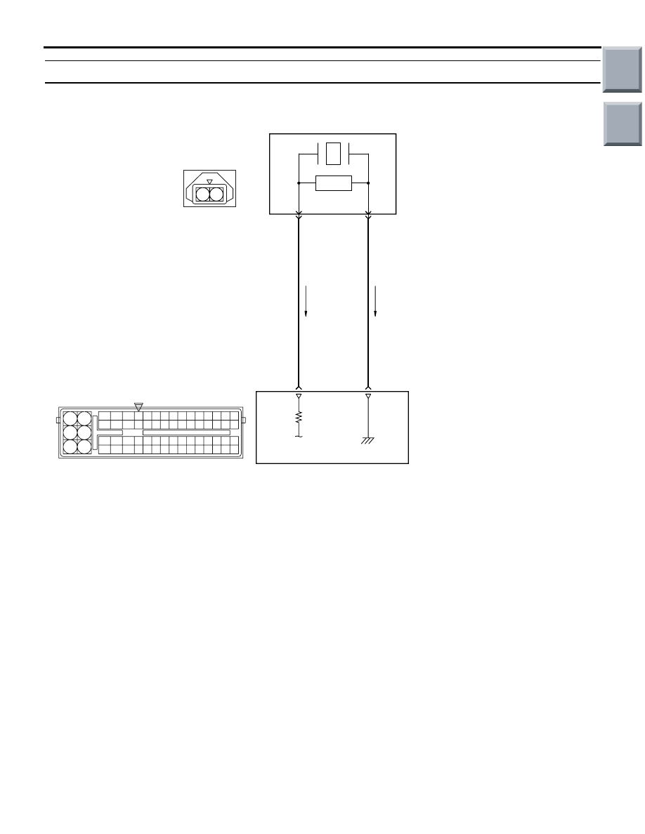
OPERATION

• A power voltage of 5 V is applied to the detona-

tion output terminal (terminal No. 2) from the 
engine-ECU <M/T> or engine-CVT-ECU <CVT> 
(terminal No. 20).

• The power voltage is earthed to the engine-ECU 

<M/T> or engine-CVT-ECU <CVT> (terminal No. 
21) from the detonation sensor (terminal No. 1).

FUNCTION

• The detonation sensor detects the vibration of the 

cylinder block caused by detonation waves, and 
inputs a signal to the engine-ECU <M/T> or 
engine-CVT-ECU <CVT>.

• In response to the signal, the engine-ECU <M/T> 

or engine-CVT-ECU <CVT> provides controls to 
retard the ignition timing when the detonation 
occurs.

TROUBLE JUDGMENT

Check Conditions

• After 2 seconds have passed since the engine 

starting sequence was completed.

• The engine speed is above 2,500 r/min <M/T>.

• The intake manifold pressure is above specified 

value <M/T>.

Judgment Criterion

• When change in detonation sensor output volt-

age is feeble for 200 consecutive times.

PROBABLE CAUSES

• Failed detonation sensor

• Open/short circuit in detonation sensor circuit or 

loose connector contact

• Failed engine-ECU <M/T> or engine-CVT-ECU 

<CVT>

AK402688

1 2

19

21

20

18

17

16

15

14

1213

11

8 9

L

10

37
52 53 54 555657585960616263646566

38 39 404142434445464748495051

22 23 24 252627282930313233343536

7

5

3

1

6

4

2

20

21

Detonation sensor

B

R

2

1

A-128

A-114

Detonation Sensor Circuit

AC

Engine-ECU <M/T> or
engine-CVT-ECU <CVT>

Wire colour code
B: Black  LG: Light green  G: Green  L: Blue  W: White  Y: Yellow  SB: Sky blue  BR: Brown  O: Orange  GR: Gray
R: Red  P: Pink  V: Violet  Pu: Purple

Main

Index

Group

TOC

TROUBLESHOOTING

MULTIPORT FUEL INJECTION (MPI) <4A9>

13A-131

DIAGNOSIS PROCEDURE

STEP 1. Connector check: A-128 detonation 
sensor connector

Q: Is the check result normal? 

YES : 

Go to Step 2 .

NO : 

Repair or replace the connector.

STEP 2. Perform resistance measurement at 
A-128 detonation sensor connector.

• Disconnect connector, and measure at harness 

side.

• Resistance between terminal No. 1 and earth.

OK: Continuity (2 

 or less)

Q: Is the check result normal? 

YES : 

Go to Step 4 .

NO : 

Go to Step 3 .

STEP 3. Connector check: A-114 engine-ECU 
connector or engine-CVT-ECU connector 

Q: Is the check result normal? 

YES : 

Check and repair harness between A-128 

(terminal No. 1) detonation sensor 
connector and A-114 (terminal No. 21) 
engine-ECU connector or engine-CVT-ECU 
connector.

NO : 

Repair or replace the connector.

AK402014

1

2

AC

Connector: A-128

A-128

A-128 Harness side
connector

AK402014

1

2

AC

Connector: A-128

A-128

A-128 Harness side
connector

AK402745

6

4

2

5

3

1

9

7

8

10

11

12

13

14

15

16

17

18

19

20

21

22

23

24

25

26

27

28

29

30

31

32

33

34

35

36

37

38

39

40

41

42

43

44

45

46

47

48

49

50

51

52

53

54

55

56

57

58

59

60

61

62

63

64

65

66

L

AD

A-114

Connector: 

A-114

Harness side connector

Engine-ECU <M/T> or
engine-CVT-ECU <CVT>

Battery

AK402014

1

2

AC

Connector: A-128

A-128

A-128 Harness side
connector

Main

Index

Group

TOC

TROUBLESHOOTING

MULTIPORT FUEL INJECTION (MPI) <4A9>

13A-132

STEP 4. Connector check: A-114 engine-ECU 
connector or engine-CVT-ECU connector 

Q: Is the check result normal? 

YES : 

Go to Step 5 .

NO : 

Repair or replace the connector.

STEP 5. Check harness between A-128 (terminal 
No. 2) detonation sensor connector and A-114 
(terminal No. 20) engine-ECU connector or 
engine-CVT-ECU connector 

• Check output line for open/short circuit and dam-

age.

Q: Is the check result normal? 

YES : 

Go to Step 6 .

NO : 

Repair the damaged harness wire.

STEP 6. M.U.T.-III diagnosis code. 

• Reconfirmation of diagnosis code.

Q: Is the diagnosis code set?

YES : 

Go to Step 7 .

NO : 

Intermittent malfunction (Refer to GROUP 
00 

− How to Use Troubleshooting/Inspection 

Service Points 

− How to Cope with 

Intermittent Malfunctions 

P.00-13

).

AK402745

6

4

2

5

3

1

9

7

8

10

11

12

13

14

15

16

17

18

19

20

21

22

23

24

25

26

27

28

29

30

31

32

33

34

35

36

37

38

39

40

41

42

43

44

45

46

47

48

49

50

51

52

53

54

55

56

57

58

59

60

61

62

63

64

65

66

L

AD

A-114

Connector: 

A-114

Harness side connector

Engine-ECU <M/T> or
engine-CVT-ECU <CVT>

Battery

AK402014

1

2

AC

Connector: A-128

A-128

A-128 Harness side
connector

AK402745

6

4

2

5

3

1

9

7

8

10

11

12

13

14

15

16

17

18

19

20

21

22

23

24

25

26

27

28

29

30

31

32

33

34

35

36

37

38

39

40

41

42

43

44

45

46

47

48

49

50

51

52

53

54

55

56

57

58

59

60

61

62

63

64

65

66

L

AD

A-114

Connector: 

A-114

Harness side connector

Engine-ECU <M/T> or
engine-CVT-ECU <CVT>

Battery

Main

Index

Group

TOC

TROUBLESHOOTING

MULTIPORT FUEL INJECTION (MPI) <4A9>

13A-133

STEP 7. Reconfirm the diagnosis code after 
replacing the detonation sensor.

• Reconfirm the diagnosis code after replacing the 

detonation sensor.

Q: Is the diagnosis code set?

YES : 

Replace the engine-ECU <M/T> or 

engine-CVT-ECU <CVT>.

NO : 

Check end.

Main

Index

Group

TOC


Content   ..  42  43  44  45   ..